


PG9602™ OPERATION AND MAINTENANCE MANUAL
© 2011 Fluke Calibration
Page
44
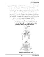
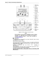
To install the AMH on the PG9000 platform, proceed as follows (see Figure 16).
Prepare the AMH:
Before loading the masses, perform the AMH
initialization procedure described in Section 2.4.10. This assures that the
AMH mass selection columns and pins are all correctly positioned.
Make sure that the mass lifting shaft is NOT installed on the mass bell.
Lower the AMH onto the PG9000 Platform:
Grasping the AMH by the
horizontal platform in its middle, lift the AMH above the PG9000 platform
and masses. Align it so that the cable and pneumatic connections line up
with the connections on the rear side of the PG Base. Center the AMH over
the mass load and gently lower it down until the AMH feet enter the holes in
the PG9000 Platform.
Assure that all three feet fully enter and seat in
the platform holes.
Tighten the platform set screws using a 2.5 mm allen
wrench provided in the AMH accessories, one for each of the feet.
Install the mass lifting shaft:
Slip the threaded end of the shaft down through
the hole in the center of the mass lifter. Thread the shaft into the binary mass
carrier by holding and rotating the trim mass tray. Note that shaft has a left
hand thread so it must be rotated counter-clockwise to tighten it. Use the 3 mm
allen wrench T-bar supplied in the AMH-100 accessories to tighten the
assembly until you feel the mass start to rotate.
Caution
Be sure that the mass lifting shaft is fully threaded into the
binary mass carrier. Thread it by hand, then tighten it using the
allen wrench supplied with the AMH until you feel the masses
rotate. If the mass lifting shaft is not fully threaded, the mass
will not align properly with the AMH mass handling columns
and pins and damage may result.
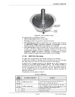
Connect the AMH drive, vent and electrical connections:
The drive and
vent connections are quick connect fittings. Drive is designated by a red
band. Vent is designated by a blue band. Mate the AMH power and signal
cable to the connector on the PG base.
If preparing to operate with vacuum under the bell jar, place the Bell
Jar onto the PG9000 platform:
Using the handles on the sides lift the Bell Jar
above the PG9000 platform and masses. Center it over the mass load and
gently lower it down until the bottom circumference of the Bell Jar reaches the
PG9000 vacuum plate. Check that the vacuum chamber is well aligned on the
vacuum plate. The Bell Jar may be rotated on the platform to the most
convenient position. Make the reference vacuum connection if the KF40
connection on the side of the AMH is being used.
If preparing to operate with vacuum under the bell jar, make sure the
vacuum vent line is connected to a vacuum pump and not open to
atmosphere. If operating without vacuum in the bell jar, open the AMH
Vent port atmosphere.
The PG9000 with AMH is now ready to operate (see Section 3).
Caution
Do not operate the AMH when using a PG9000 in “absolute by
vacuum” mode without
having a vacuum supply connected to
AMH-100’s Drive Vacuum port. Always check that the AMH is
supplied with vacuum before establishing reference vacuum in
the bell jar. Do not plug the AMH drive vacuum port. Doing so
may result in damage to the binary mass pins and/or binary
masses (see Section
Summary of Contents for PG9000 Series
Page 10: ...PG9602 OPERATION AND MAINTENANCE MANUAL 2011 Fluke Calibration Page X Notes...
Page 128: ...PG9602 OPERATION AND MAINTENANCE MANUAL 2011 Fluke Calibration Page 118 Notes...
Page 164: ...PG9602 OPERATION AND MAINTENANCE MANUAL 2011 Fluke Calibration Page 154 Notes...
Page 188: ...PG9602 OPERATION AND MAINTENANCE MANUAL 2011 Fluke Calibration Page 178 Notes...
Page 192: ...PG9602 OPERATION AND MAINTENANCE MANUAL 2011 Fluke Calibration Page 182 Notes...


