


OF-500 OptiFiber Certifying OTDR
Technical Reference Handbook
3-38
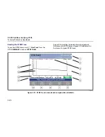
OTDR DETAILS Screens
The
OTDR DETAILS
screens show additional OTDR test
information and measurements, some of which is
described below. Press
H
from the
OTDR DETAILS
screen for more information on these screens.
Warning Messages
Warnings occur when a value could not be reliably
determined. These values are usually preceded by a "<"
or ">" (less than or greater than) symbol. This may occur
if the fiber is too long, the signal is weak, events are too
close together to distinguish measurements, or a
measurement is beyond the tester's range.
Attenuation Coefficient
The attenuation per kilometer for the entire length of
the cabling. This value may not be shown if it could not
be measured accurately.
ORL (Optical Return Loss)
The difference between the power of the OTDR's test
pulse and the power of the light reflected back to the
OTDR from the fiber, connectors, splices, and faults along
the fiber. Larger ORL values mean less light is reflected
back, which corresponds to better fiber performance. For
example, a fiber with an ORL of 40 dB reflects less light
back to a source than a fiber with an ORL of 32 dB.
Segment Attenuation Coefficient
The attenuation per kilometer for the fiber segment
before the event. This value may not be shown if it could
not be measured accurately. This can occur on short
segments or if the connector before the segment has
excessive tailing.
Reflectance
The difference between the power of the OTDR's test
pulse and the power of the light reflected back to the
OTDR from an event. A smaller (more negative)
reflectance value means less light is reflected back. For
example, a good connection may have a reflectance of
-45 dB. A dirty connection that reflects more light back to
the OTDR may have a reflectance of -20 dB.
Reflectances that exceed the tester's measurement range
are marked with ">" (greater than). If any reflection is
marked with ">", ORL is marked with "<" (less than).
Reflectances from hidden events may be marked with
“<" because the tester cannot measure the backscatter
before the event.
Reflectance measurements are affected by the
backscatter value entered on the
Cable
tab in Setup.
Summary of Contents for OF-500 OptiFiber
Page 12: ...OF 500 OptiFiber Technical Reference Handbook x ...
Page 18: ...OF 500 OptiFiber Technical Reference Handbook xvi ...
Page 27: ...Getting Acquainted Powering the Tester 1 1 9 ajt20f eps Figure 1 1 Battery Pack Features ...
Page 29: ...Getting Acquainted Verifying Operation 1 1 11 ajt56f eps Figure 1 2 Removing the Module ...
Page 46: ...OF 500 OptiFiber Certifying OTDR Technical Reference Handbook 1 28 ...
Page 136: ...OF 500 OptiFiber Certifying OTDR Technical Reference Handbook 4 6 ...
Page 192: ...OF 500 OptiFiber Certifying OTDR Technical Reference Handbook 6 48 ...
Page 254: ...OF 500 OptiFiber Certifying OTDR Technical Reference Handbook 11 36 ...
Page 256: ...OF 500 OptiFiber Certifying OTDR Technical Reference Handbook ...
Page 272: ...B 14 OF 500 OptiFiber Certifying OTDR Technical Reference Handbook ...
Page 274: ...OF 500 OptiFiber Certifying OTDR Technical Reference Handbook C 2 ...
Page 282: ...OF 500 OptiFiber Technical Reference Handbook 8 ...


