SECTION 2 : DESCRIPTION OF CONTROLS AND INDICATORS
2.1.
INTRODUCTION
Section 2 describes the location of the controls and indicators on the Instructor Station and those within
the instructor’s compartment that pertain to flight training and emergency procedures.
2.2.
EXTERIOR CONTROLS AND INDICATORS
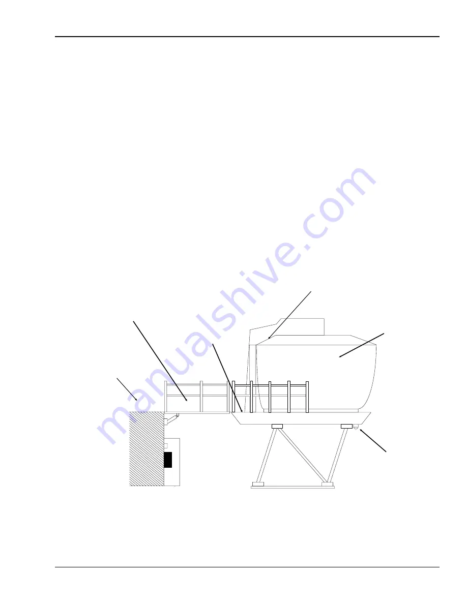
The following figures illustrate a typical layout of a FlightSafety Simulator. Figure 2-1 illustrates the
exterior view and Figure 2-2 illustrates the floor plan of a simulator.
AWRAMP.GEM
Access
Ramp
Instructor
Compartment
Back
Porch
Exterior
Platform
Cockpit, or
Student
Station
On Motion
Warning
Lamp
Figure 2-1. Exterior View Of Simulator
TM-3-B 737-IOS1-007
EXTERIOR CONTROLS AND INDICATORS
FSI-SSD
2-1
Operation (NT IOS)
B 737
JAN 2001


