ELECTRICAL
Page G-8
Repair and Service Manual
Read all of Section B and this section before attempting any procedure. Pay particular attention to all Notes, Cautions and Warnings
FUEL CUT SOLENOID
The fuel cut solenoid is located in the carburetor and
shuts off the flow of fuel to the carburetor main jet when
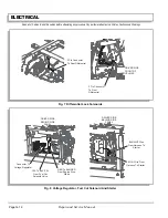
the key switch is OFF (Ref Fig. 8 on page G-12). If the
vehicle won’t start, confirm the ignition system is func-
tioning, the air cleaner is not plugged and that there is
fuel in the tank and fuel filter. If all of these items are
working correctly, raise the seat and turn the key switch
ON and OFF. The sound of the solenoid should be heard
as it opens when the key is turned to ON. If no sound is
heard, the solenoid is suspect. Disconnect the wiring har-
ness and check for voltage when the key switch is ON. If
battery voltage is present, replace the solenoid (Refer to
Honda GX610 Repair Manual for V-Twin Overhead Valve
engine). If battery voltage is not present, check that wire
harness does not have an internal break.
NEUTRAL SWITCH
To prevent serious per-
sonal injury or death
from inadvertent move-
ment of vehicle, all tests performed requiring starter/
generator or engine to rotate must be performed by
lifting vehicle (see Section B).
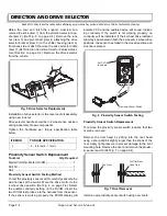
The neutral switch is located on the transmission and
prevents the vehicle from being started if the direction
selector is in gear (Ref Fig. 6 on page G-11). If the starter
will not operate, be sure that the direction selector is in
neutral. If the starter still does not operate, check the in
line fuse (25 amp) mounted on the driver side under the
cowl. If the fuse is good, turn the key switch to ON and
remove the wiring harness from the neutral switch.
Check for voltage between the two terminals at the har-
ness. Turn key switch to OFF. If voltage is present, insert
a jumper wire between the two wire harness terminals
and turn key switch to start. If the starter operates,
replace the neutral switch. If battery voltage is not
present, check that wire harness does not have an inter-
nal break.
HEADLIGHTS
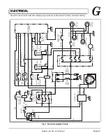
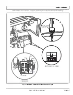
The headlights are wired in parallel to the light switch
(Ref Fig. 4 on page G-9). If one light is working, check
the other for continuity through the filament. If there is no
continuity, the bulb has blown and must be replaced. If
both bulbs are out, first check the fuse. If the fuse is good
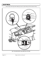
check the switch for continuity and replace the switch if
continuity is not present with the switch on (Ref Fig. 5 on
page G-10). If the switch is good, check that the wire har-
ness does not have an internal break.
TAILLIGHT (ACCESSORY)
The taillight is wired in parallel with the headlights, there-
fore if the one or both headlights are operating, the prob-
lem lies with the bulb, socket or wiring.
BRAKE SWITCH
The brake light switch is a hydraulic pressure switch
attached to the front reservoir of the master cylinder. If
the brake light does not operate, the most likely cause is
the fuse, bulb, socket or wiring. Apply the brakes and
check for voltage at the bulb socket. If no voltage is
present and the fuse and wiring are good, check the
brake light switch. With the brake pedal depressed, there
should be continuity between the switch terminals. If not
replace the switch and refer to BRAKES SECTION for
brake bleeding instructions.
POWER OUTLET
Check the power outlet by checking for battery voltage at
the outlet. If battery voltage is not present, check the fuse
and that the wire harness does not have an internal
break.
!
!
Summary of Contents for ST 4X4
Page 6: ...Page iv Repair and Service Manual TABLE OF CONTENTS Notes...
Page 10: ...Repair and Service Manual SAFETY INFORMATION Page viii Notes...
Page 12: ...GENERAL INFORMATION ROUTINE MAINTENANCE Page A ii Repair and Service Manual Notes...
Page 24: ...SAFETY Page B ii Repair and Service Manual Notes...
Page 34: ...BODY AND TRUCKBED Page C ii Repair and Service Manual Notes...
Page 50: ...BRAKES Page D ii Repair and Service Manual Notes...
Page 68: ...CONTINUOUSLY VARIABLE TRANSMISSION CVT Page E ii Repair and Service Manual Notes...
Page 74: ...DIRECTION AND DRIVE SELECTOR Page F ii Repair and Service Manual Notes...
Page 80: ...ELECTRICAL Page G ii Repair and Service Manual Notes...
Page 114: ...FRONT SUSPENSION AND STEERING Page J ii Repair and Service Manual Notes...
Page 128: ...FUEL SYSTEM Page K ii Repair and Service Manual Notes...
Page 136: ...PAINT Page L ii Repair and Service Manual Notes...
Page 142: ...REAR AXLE AND SUSPENSION Page M ii Repair and Service Manual Notes...
Page 152: ...SPEED CONTROL Page N ii Repair and Service Manual Notes...
Page 160: ...TROUBLESHOOTING Page P ii Repair and Service Manual Notes...
Page 168: ...WHEELS AND TIRES Page R ii Repair and Service Manual Notes...
Page 174: ...GENERAL SPECIFICATIONS Page S ii Repair and Service Manual Notes...
Page 180: ...LIMITED WARRANTY Page T ii Repair and Service Manual Notes...
Page 182: ...Page T 2 Repair and Service Manual LIMITED WARRANTY Notes...

