ENGINE AND TRANSMISSION
Page H-8
Repair and Service Manual
Read all of Section B and this section before attempting any procedure. Pay particular attention to all Notes, Cautions and Warnings
In the following text, there are references to
removing/installing bolts, etc. Additional hard-
ware (nuts, washers, etc.) that is removed must always be
installed in its original position unless otherwise specified. Non
specified torque figures are as shown in the table contained in
Section A.
Note the location of wires, wire ties and clamps before removal
and always install them in their original location. Use of mask-
ing tape to label wires is recommended.
The engine will be lifted out between differential and wide
crossmember of frame.
Tool List
Qty. Required
Ratchet, 3/8" drive ....................................................... 1
Torque wrench, 3/8" drive, ft. lbs ................................. 1
Impact wrench, 1/2" drive ............................................ 1
Socket, 12mm, 3/8" drive ............................................ 1
Socket, 1/2", 3/8" drive ................................................ 1
Deep well socket, 17mm, 3/8" drive ............................ 1
Impact socket, 5/8", 1/2" drive ..................................... 1
Impact socket, 13/16", 1/2" drive ................................. 1
Allen wrench, 3/16", 3/8" drive .................................... 1
Wrench, 1/4"................................................................ 1
Wrench, 10mm ............................................................ 1
Wrench, 1/2"................................................................ 2
Wrench, 3/4"................................................................ 1
Insulated wrench, 1/2" ................................................. 1
Straight blade screwdriver ........................................... 1
Needle nose pliers....................................................... 1
Pliers ........................................................................... 1
Masking tape ............................................................ AR
Back brace .................................................................. 2
Oil drain pan ................................................................ 1
Utility knife ................................................................... 1
Shop rag, clean ........................................................ AR
Plug, for fuel line.......................................................... 1
Cap, for fuel pump....................................................... 1
Release the handle and raise the truck bed. Remove gas
spring (Ref Gas Spring Replacement in BODY AND
TRUCK BED).
If engine is to be repaired, not replaced, wash engine
and chassis to remove dirt build-up.
Disconnect negative (-) cable from battery to prevent
electrical shorts that could cause an explosion. Remove
seat bottom (Ref Seat bottom Replacement in BODY
AND TRUCK BED). Remove seat cross member.
Drain oil from engine.
CVT Back Cover Removal
Remove the CVT back cover (Ref CVT BACK COVER
REPLACEMENT section on page H-7).
Exhaust Pipe And Exhaust Manifold Removal
Note location and disconnect wire from oil pressure
switch located above oil filter and free from any wire ties
or clamps anchoring it to engine. Remove the spring and
remove the exhaust pipe from muffler (Ref MUFFLER
REPLACEMENT section on page H-11). Remove the
exhaust manifold (Ref EXHAUST MANIFOLD
REPLACEMENT section on page H-12)
Do not smoke and wear eye protection before opening
the fuel system. Provided ventilation is adequate,
remove and plug fuel line from fuel pump and cap fuel
pump nipple.
Disconnecting Starter Wires
Note location of starter wires and remove from starter.
Air Intake System Removal
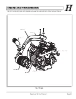
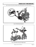
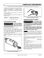
Remove the clamp (item 1) using straight blade screw-
driver and disconnect remote air hose (item 2) from air
cleaner (item 3) (Ref Fig. 15 on page H-9). Remove air
cleaner cover (item 4) and filter (item 5). Remove the
bolts (item 6) using 10mm wrench and the washers (item
7). Remove air intake plenum (item 8).
Remove the bolts (item 9) using 1/2" wrench, that mount
air filter bracket (item 10) to engine. Hold the bolt (item
11) and remove the nut (item 12). Remove the washers
(item 13). Remove bracket.
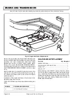
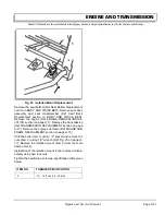
Accelerator, Governor and Choke Cable Removal
To prevent any debris falling into engine, cover carbure-
tor with a clean shop rag and hold in place with a rubber
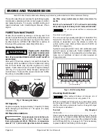
band. Remove accelerator cable (item 1) (Ref Fig. 16 on
page H-9). Remove the bolts (item 2) using 12mm
wrench and remove governor cable (item 3) and choke
bracket (item 4). Remove choke cable connected to the
engine (Ref Choke Cable Replacement in FUEL SYS-
TEM).
Summary of Contents for ST 4X4
Page 6: ...Page iv Repair and Service Manual TABLE OF CONTENTS Notes...
Page 10: ...Repair and Service Manual SAFETY INFORMATION Page viii Notes...
Page 12: ...GENERAL INFORMATION ROUTINE MAINTENANCE Page A ii Repair and Service Manual Notes...
Page 24: ...SAFETY Page B ii Repair and Service Manual Notes...
Page 34: ...BODY AND TRUCKBED Page C ii Repair and Service Manual Notes...
Page 50: ...BRAKES Page D ii Repair and Service Manual Notes...
Page 68: ...CONTINUOUSLY VARIABLE TRANSMISSION CVT Page E ii Repair and Service Manual Notes...
Page 74: ...DIRECTION AND DRIVE SELECTOR Page F ii Repair and Service Manual Notes...
Page 80: ...ELECTRICAL Page G ii Repair and Service Manual Notes...
Page 114: ...FRONT SUSPENSION AND STEERING Page J ii Repair and Service Manual Notes...
Page 128: ...FUEL SYSTEM Page K ii Repair and Service Manual Notes...
Page 136: ...PAINT Page L ii Repair and Service Manual Notes...
Page 142: ...REAR AXLE AND SUSPENSION Page M ii Repair and Service Manual Notes...
Page 152: ...SPEED CONTROL Page N ii Repair and Service Manual Notes...
Page 160: ...TROUBLESHOOTING Page P ii Repair and Service Manual Notes...
Page 168: ...WHEELS AND TIRES Page R ii Repair and Service Manual Notes...
Page 174: ...GENERAL SPECIFICATIONS Page S ii Repair and Service Manual Notes...
Page 180: ...LIMITED WARRANTY Page T ii Repair and Service Manual Notes...
Page 182: ...Page T 2 Repair and Service Manual LIMITED WARRANTY Notes...

