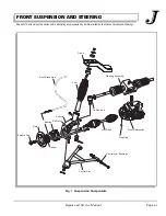
FRONT SUSPENSION AND STEERING
Page J-7
Repair and Service Manual
Read all of Section B and this section before attempting any procedure. Pay particular attention to all Notes, Cautions and Warnings
Replace the front wheels as per the WHEELS AND
TIRES section and lower vehicle.
Half Shaft Replacement
Use a commercially available Anti-Seize com-
pound on all splines.
Tool List
Qty. Required
Ratchet, 1/2" drive....................................................... 1
Torque wrench, 1/2" drive, 165 ft. lbs capacity............ 1
Extension, 6", 1/2" drive .............................................. 1
Socket, 9/16", 1/2" drive.............................................. 1
Allen wrench, 5/16", 1/2" drive .................................... 1
Wrench, 3/4"................................................................ 1
Wrench, 9/16".............................................................. 1
Plastic faced hammer.................................................. 1
Straight blade screwdriver ........................................... 1
Needle nose pliers....................................................... 1
Pry bar......................................................................... 1
Floor jack..................................................................... 1
Jack stands ................................................................. 2
Wheel chocks .............................................................. 4
Loosen the four nuts on the front wheel half turn.
Lift and support front of the vehicle per SAFETY section.
Remove the wheels (Ref Wheels and Brake Removal
Section on page J-2). Remove the tie rod end (Ref Tie
Rod End Removal Section on page J-2). Tap off the con-
trol arm end from the steering knuckle (item 4) (Ref Con-
trol Arm (Knuckle End Removal) Section on page J-3).
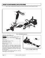
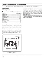
Remove the half shaft (item 2) using pry bar to separate
it from the front differential (Ref Fig. 9 on page J-8).
Remove the hog ring (item 3).
The installation of the half shaft is the reverse of disas-
sembly using new cotter pins and new hog rings.
Replace the front wheels as per the WHEELS AND
TIRES section and lower vehicle.
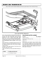
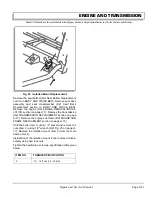
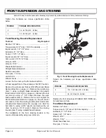
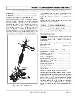
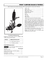
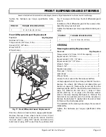
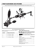
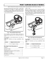
Fig. 8 Ball Joint Replacement
ITEM NO
TORQUE SPECIFICATION
2
135 - 165 ft.lbs (183 - 224 Nm)
5
13 - 15 ft.lbs (18 - 20 Nm)
7
4
1
2
3
6
5
Summary of Contents for ST 4X4
Page 6: ...Page iv Repair and Service Manual TABLE OF CONTENTS Notes...
Page 10: ...Repair and Service Manual SAFETY INFORMATION Page viii Notes...
Page 12: ...GENERAL INFORMATION ROUTINE MAINTENANCE Page A ii Repair and Service Manual Notes...
Page 24: ...SAFETY Page B ii Repair and Service Manual Notes...
Page 34: ...BODY AND TRUCKBED Page C ii Repair and Service Manual Notes...
Page 50: ...BRAKES Page D ii Repair and Service Manual Notes...
Page 68: ...CONTINUOUSLY VARIABLE TRANSMISSION CVT Page E ii Repair and Service Manual Notes...
Page 74: ...DIRECTION AND DRIVE SELECTOR Page F ii Repair and Service Manual Notes...
Page 80: ...ELECTRICAL Page G ii Repair and Service Manual Notes...
Page 114: ...FRONT SUSPENSION AND STEERING Page J ii Repair and Service Manual Notes...
Page 128: ...FUEL SYSTEM Page K ii Repair and Service Manual Notes...
Page 136: ...PAINT Page L ii Repair and Service Manual Notes...
Page 142: ...REAR AXLE AND SUSPENSION Page M ii Repair and Service Manual Notes...
Page 152: ...SPEED CONTROL Page N ii Repair and Service Manual Notes...
Page 160: ...TROUBLESHOOTING Page P ii Repair and Service Manual Notes...
Page 168: ...WHEELS AND TIRES Page R ii Repair and Service Manual Notes...
Page 174: ...GENERAL SPECIFICATIONS Page S ii Repair and Service Manual Notes...
Page 180: ...LIMITED WARRANTY Page T ii Repair and Service Manual Notes...
Page 182: ...Page T 2 Repair and Service Manual LIMITED WARRANTY Notes...

