ELECTRICAL
Page G-5
Repair and Service Manual
Read all of Section B and this section before attempting any procedure. Pay particular attention to all Notes, Cautions and Warnings
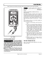
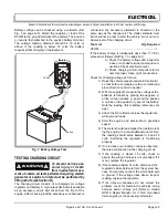
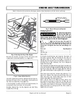
Battery voltage can be checked using a voltmeter (Ref
Fig. 3 on page G-5). Attach the negative (-) lead of the
DVOM to the ground terminal of the battery. The positive
(+) lead is then attached to the positive battery terminal.
The voltage reading obtained should be 12 volts or
above. If the reading is below 12 volts, the battery
requires either charging or replacement.
TESTING CHARGING CIRCUIT
To prevent serious per-
sona l injury or death
from inadvertent move-
ment of vehicle, all tests performed requiring starter/
generator or engine to rotate must be performed by
lifting vehicle (see Section B).
The charging circuit consists of a charging coil, voltage
regulator and battery. A high output alternator is available
as an accessory and is belt driven from the front of the
engine. After checking that the accessory wire harness is
connected, the accessory alternator is checked in the
same way as the charge coil. The starter solenoid must
be functional in order to start the vehicle, but is not con-
sidered part of the charging circuit.
Tool List
Qty. Required
DVOM.......................................................................... 1
If the battery charge is inadequate (less than 11 VDC),
proceed as follows (Ref Fig. 1 on page G-1):
a) Check the battery voltage and inspect for
loose or corroded terminal posts and con-
nections. Check electrolyte level.
b) Check charging circuit component termi-
nals for proper, clean, tight connections.
Check for charging voltage as follows:
1) Raise the vehicle (see procedure in Section B)
so that both rear wheels are free to rotate and
place direction control in neutral.
2) With the engine off, measure the voltage at the
battery’s terminals by placing the negative (-)
probe on the negative (-) post and the positive
(+) probe on the positive (+) post of the battery.
Note the reading (this is battery reference volt-
age).
3) Attach the DC voltmeter across the regulator’s
white ground leads.
4) Start the engine and accelerate to governed
speed.
5) The meter should read higher than before start-
ing the engine. In a reasonable amount of time,
the reading should settle between 14 and 15
volts, indicating the regulator is functioning
properly.
6) If no increase over battery voltage is observed,
there is a malfunction in the charging circuit.
7) If the reading is above 15 volts, check to
assure the wiring harness is not grounded. If it
is not, replace the regulator.
8) If the reading is below 14 volts, disconnect the
regulator’s white field wire from the system har-
ness. Temporarily connect the white field wire
to ground. If the voltage rises above its prior
reading, replace the regulator.
9) If the above procedures do not correct the
problem, check for faults in the vehicles wiring
harness and/or charge coil (Refer to Honda
GX610 Repair Manual for V-Twin Overhead
Valve engine) or the accessory alternator.
Fig. 3 Battery Voltage Test
Battery
DVOM
!
!
Summary of Contents for ST 4X4
Page 6: ...Page iv Repair and Service Manual TABLE OF CONTENTS Notes...
Page 10: ...Repair and Service Manual SAFETY INFORMATION Page viii Notes...
Page 12: ...GENERAL INFORMATION ROUTINE MAINTENANCE Page A ii Repair and Service Manual Notes...
Page 24: ...SAFETY Page B ii Repair and Service Manual Notes...
Page 34: ...BODY AND TRUCKBED Page C ii Repair and Service Manual Notes...
Page 50: ...BRAKES Page D ii Repair and Service Manual Notes...
Page 68: ...CONTINUOUSLY VARIABLE TRANSMISSION CVT Page E ii Repair and Service Manual Notes...
Page 74: ...DIRECTION AND DRIVE SELECTOR Page F ii Repair and Service Manual Notes...
Page 80: ...ELECTRICAL Page G ii Repair and Service Manual Notes...
Page 114: ...FRONT SUSPENSION AND STEERING Page J ii Repair and Service Manual Notes...
Page 128: ...FUEL SYSTEM Page K ii Repair and Service Manual Notes...
Page 136: ...PAINT Page L ii Repair and Service Manual Notes...
Page 142: ...REAR AXLE AND SUSPENSION Page M ii Repair and Service Manual Notes...
Page 152: ...SPEED CONTROL Page N ii Repair and Service Manual Notes...
Page 160: ...TROUBLESHOOTING Page P ii Repair and Service Manual Notes...
Page 168: ...WHEELS AND TIRES Page R ii Repair and Service Manual Notes...
Page 174: ...GENERAL SPECIFICATIONS Page S ii Repair and Service Manual Notes...
Page 180: ...LIMITED WARRANTY Page T ii Repair and Service Manual Notes...
Page 182: ...Page T 2 Repair and Service Manual LIMITED WARRANTY Notes...


