DIRECTION AND DRIVE SELECTOR
Page F-4
Repair and Service Manual
Read all of Section B and this section before attempting any procedure. Pay particular attention to all Notes, Cautions and Warnings
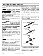
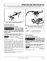
Raise the cowl and latch the support. Unscrew and
remove the knob (item 1) from the direction selector han-
dle (item 2) (Ref Fig. 5 on page F-4). Remove the lock
nut (item 3) and pivot shaft (item 4) attaching the drive
selector bracket (item 5) to the shifter housing (item 6)
from back side of dash. Remove the drive selector cable
(item 7) (Ref Direction And Drive Selector Cables Adjust-
ment Section on page F-2). Remove the drive selector
from the vehicle.
Installation of drive selector is the reverse of disassembly
using new lock nut.
Drive selector handle should be in 2 wheel drive position
during assembly of new components.
Tighten the hardware per torque specification table
below.
Proximity Sensor Switch Replacement
Tool List
Qty. Required
Digital Volt Ohm Meter (DVOM) .................................. 1
Drill bit ......................................................................... 1
Drill .............................................................................. 1
Proximity Sensor Switch Testing Method
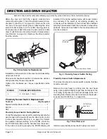
To test the proximity sensor switch, carefully separate the
wire harness at the sensor. Move the drive control to the
4 wheel drive position (Ref Fig. 6 on page F-4). Select
the audible continuity setting on the DVOM. Insert the
two DVOM test probes into the harness from the sensor.
If the sensor is working properly, the DVOM display will
indicate 00.0 and the audible device will sound, indicat-
ing continuity. If the switch is not working properly, no
continuity will be indicated. If the 4 wheel drive indicator
light stays illuminated in both the 2 wheel & 4 wheel drive
positions, the sensor has failed in the closed position and
must be replaced.
Proximity Sensor Switch Replacement
To remove the proximity sensor switch requires that two
rivets be removed:
Remove the rivet head by drilling into the rivet head
using a sharp drill bit slightly larger than the shank of the
rivet. Apply light pressure to prevent damage to the rivet
mounting hole. Remove the rivet and remove the proxim-
ity sensor switch (Ref Fig. 7 on page F-4).
Install a new proximity sensor switch using new rivets.
Fig. 5 Drive Selector Replacement
ITEM NO
TORQUE SPECIFICATION
3
6 - 8 ft. lbs (8 - 11 Nm)
4
3
5
6
7
2
1
Fig. 6 Proximity Sensor Switch Testing
Fig. 7 Rivet Removal
Proximity Sensor Switch
BEEP
Set DVOM
to audible
Pop Rivet
Drill Out Rivet
Head Only
Summary of Contents for ST 4X4
Page 6: ...Page iv Repair and Service Manual TABLE OF CONTENTS Notes...
Page 10: ...Repair and Service Manual SAFETY INFORMATION Page viii Notes...
Page 12: ...GENERAL INFORMATION ROUTINE MAINTENANCE Page A ii Repair and Service Manual Notes...
Page 24: ...SAFETY Page B ii Repair and Service Manual Notes...
Page 34: ...BODY AND TRUCKBED Page C ii Repair and Service Manual Notes...
Page 50: ...BRAKES Page D ii Repair and Service Manual Notes...
Page 68: ...CONTINUOUSLY VARIABLE TRANSMISSION CVT Page E ii Repair and Service Manual Notes...
Page 74: ...DIRECTION AND DRIVE SELECTOR Page F ii Repair and Service Manual Notes...
Page 80: ...ELECTRICAL Page G ii Repair and Service Manual Notes...
Page 114: ...FRONT SUSPENSION AND STEERING Page J ii Repair and Service Manual Notes...
Page 128: ...FUEL SYSTEM Page K ii Repair and Service Manual Notes...
Page 136: ...PAINT Page L ii Repair and Service Manual Notes...
Page 142: ...REAR AXLE AND SUSPENSION Page M ii Repair and Service Manual Notes...
Page 152: ...SPEED CONTROL Page N ii Repair and Service Manual Notes...
Page 160: ...TROUBLESHOOTING Page P ii Repair and Service Manual Notes...
Page 168: ...WHEELS AND TIRES Page R ii Repair and Service Manual Notes...
Page 174: ...GENERAL SPECIFICATIONS Page S ii Repair and Service Manual Notes...
Page 180: ...LIMITED WARRANTY Page T ii Repair and Service Manual Notes...
Page 182: ...Page T 2 Repair and Service Manual LIMITED WARRANTY Notes...


