REAR AXLE AND SUSPENSION
Page M-7
Repair and Service Manual
Read all of Section B and this section before attempting any procedure. Pay particular attention to all Notes, Cautions and Warnings
If both springs are to be replaced and the rear
axle is not to be removed, it is important to
remove and replace one spring at a time. Springs must be
replaced in sets. Never replace just one.
Tool List
Qty. Required
Floor jack, 1 1/2 ton .................................................... 1
Jack stands ................................................................. 4
Wheel chocks.............................................................. 4
Ratchet, 1/2" drive....................................................... 1
Torque wrench, 3/8" drive, ft. lbs ................................. 1
Impact wrench, 1/2" drive............................................ 1
Deep well socket, 9/16", 3/8" drive.............................. 1
Deep well socket, 3/4", 1/2" drive................................ 1
Impact socket, 9/16", 1/2" drive................................... 1
Wrench, 9/16" ............................................................. 1
Wrench, 3/4" ............................................................... 1
Needle nose pliers ...................................................... 1
Loosen the four nuts on the rear wheels half turn.
Install wheel chocks in front and behind each front wheel.
Lift the rear of the vehicle until the tires clear the ground.
Place jack stands under the rear of the frame as shown
in the LIFTING PROCEDURE in Section B of this man-
ual. Put the floor jack at the center of rear differential
being careful to locate the jack on the axle tube flanges,
lift it and place the two jack stands just inboard of the
spring pads and slightly below the rear axle tubes. The
jack stands are to prevent the rear axle from falling when
the rear axle is lowered from the rear springs. Lower the
floor jack. Ensure stability of the vehicle. Remove wheel
lug nuts using 3/4" impact socket (Refer WHEELS AND
TIRES section for wheel lug nuts torque specification).
Remove the rear wheels.
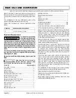
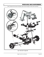
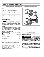
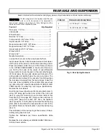
Hold the rear lower shackle and front spring bolts (item 1)
using 3/4" deep well socket and remove the lock nuts
(item 2) using 3/4" wrench (do not remove bolts at this
time) (Ref Fig. 8 on page M-7). Remove the nuts (item 3)
using 9/16" deep well socket, 3/8" drive, the washers
(item 4) and the ‘U’ bolts (item 5). Remove the leaf spring
plate (item 6) and allow the rear axle tube to rest on the
jack stand. Remove the bolts (item 1) and the rear spring
(item 7).
The installation of the rear spring is the reverse of disas-
sembly using new lock nuts.
Tighten the hardware per torque specification table
below.
Replace the rear wheels per WHEELS AND TIRES sec-
tion and lower vehicle.
ITEM NO
TORQUE SPECIFICATIONS
2
8 -10 ft. lbs (11 - 15 Nm)
3
16 - 20 ft. lbs (22 - 27 Nm)
Fig. 8 Rear Spring Removal
1
6
4
3
5
2
7
Summary of Contents for ST 4X4
Page 6: ...Page iv Repair and Service Manual TABLE OF CONTENTS Notes...
Page 10: ...Repair and Service Manual SAFETY INFORMATION Page viii Notes...
Page 12: ...GENERAL INFORMATION ROUTINE MAINTENANCE Page A ii Repair and Service Manual Notes...
Page 24: ...SAFETY Page B ii Repair and Service Manual Notes...
Page 34: ...BODY AND TRUCKBED Page C ii Repair and Service Manual Notes...
Page 50: ...BRAKES Page D ii Repair and Service Manual Notes...
Page 68: ...CONTINUOUSLY VARIABLE TRANSMISSION CVT Page E ii Repair and Service Manual Notes...
Page 74: ...DIRECTION AND DRIVE SELECTOR Page F ii Repair and Service Manual Notes...
Page 80: ...ELECTRICAL Page G ii Repair and Service Manual Notes...
Page 114: ...FRONT SUSPENSION AND STEERING Page J ii Repair and Service Manual Notes...
Page 128: ...FUEL SYSTEM Page K ii Repair and Service Manual Notes...
Page 136: ...PAINT Page L ii Repair and Service Manual Notes...
Page 142: ...REAR AXLE AND SUSPENSION Page M ii Repair and Service Manual Notes...
Page 152: ...SPEED CONTROL Page N ii Repair and Service Manual Notes...
Page 160: ...TROUBLESHOOTING Page P ii Repair and Service Manual Notes...
Page 168: ...WHEELS AND TIRES Page R ii Repair and Service Manual Notes...
Page 174: ...GENERAL SPECIFICATIONS Page S ii Repair and Service Manual Notes...
Page 180: ...LIMITED WARRANTY Page T ii Repair and Service Manual Notes...
Page 182: ...Page T 2 Repair and Service Manual LIMITED WARRANTY Notes...

