BODY AND TRUCKBED
Page C-8
4GRCKTCPF5GTXKEG/CPWCN
4GCFCNNQH5GEVKQP$CPFVJKUUGEVKQPDGHQTGCVVGORVKPICP[RTQEGFWTG2C[RCTVKEWNCTCVVGPVKQPVQCNN0QVGU%CWVKQPUCPF9CTPKPIU
Torx bit screwdriver T- 45............................................ 1
Torx bit, 3/8", drive T- 45 ............................................. 1
Park vehicle on a level surface. Engage park brake.
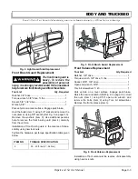
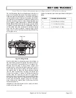
Remove the cowl assembly (Ref Cowl Replacement
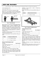
Section on page C-5). Remove rivets (item 1) using drill
and a sharp drill bit (Ref Fig. 11 on page C-8).
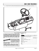
Remove steering wheel (item 2) (Refer Steering Wheel
Replacement section in FRONT SUSPENSION AND
STEERING). Hold the nuts (item 3) using 1/2" wrench,
and remove the bolts (item 4) using Torx bit screwdriver
(Ref Fig. 10 on page C-7). Hold the bolts (item 5) using
1/2" wrench, and remove the nuts (item 6) using 1/2"
socket. Pull the instrument panel (item 7) up and over
steering column.
Installation of instrument panel is reverse of disassembly
using new lock nuts and rivets.
Tighten the hardware per torque specification table given
below.
Rocker Panel Replacement
Tool List
Qty. Required
Torque wrench, 3/8" drive, ft. lbs................................. 1
Socket, 7/16", 3/8" drive .............................................. 1
Wrench, 7/16".............................................................. 1
Phillips head screwdriver............................................. 1
Park vehicle on a level surface. Engage park brake.
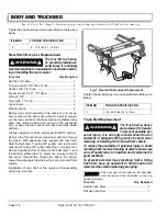
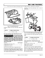
Hold the bolts (item 1) using Phillips head screwdriver
and remove the nuts (item 2) using 7/16" wrench
,
(Ref
Fig. 12 on page C-8). Pull the rocker panel (item 3) from
the side and remove it.
Installation of rocker panel is reverse of disassembly
using new lock nuts.
Tighten the hardware per torque specification table given
below.
Floorpan Replacement
Tool List
Qty. Required
Torque wrench, 3/8" drive, ft. lbs ................................. 1
Socket, 7/16", 3/8" drive .............................................. 1
Wrench, 7/16" .............................................................. 1
Phillips head screwdriver ............................................. 1
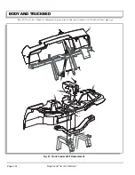
Park vehicle on a level surface. Engage park brake.
Remove rocker panel (Ref Rocker Panel Replacement
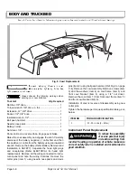
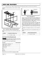
Section on page C-8). Hold the nut (item 1) using 7/16"
wrench and loosen the bolt (item 2) using 7/16" socket
and remove the bolts (item 2) using Phillips head screw-
driver (Ref Fig. 13 on page C-9). Remove the floorpan
(item 3).
Installation of floorpan is reverse of disassembly using
new lock nuts.
Replace the old foam pads (item 4) with the new ones if
deteriorated or adhered to the old floor pan (item 3).
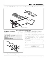
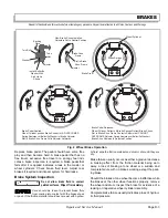
Fig. 11 Rivet Removal
ITEM NO
TORQUE SPECIFICATION
4
15 - 19 ft. lbs (20 - 25 Nm)
6
11 - 15 ft. lbs (15 - 20 Nm)
Pop Rivet
Drill Out Rivet
Head Only
ITEM NO
TORQUE SPECIFICATION
2
7 - 12 ft. lbs (9 - 16 Nm)
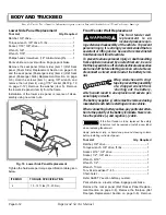
Fig. 12 Rocker Panel Replacement
1
2
3
Summary of Contents for ST 4X4
Page 6: ...Page iv Repair and Service Manual TABLE OF CONTENTS Notes...
Page 10: ...Repair and Service Manual SAFETY INFORMATION Page viii Notes...
Page 12: ...GENERAL INFORMATION ROUTINE MAINTENANCE Page A ii Repair and Service Manual Notes...
Page 24: ...SAFETY Page B ii Repair and Service Manual Notes...
Page 34: ...BODY AND TRUCKBED Page C ii Repair and Service Manual Notes...
Page 50: ...BRAKES Page D ii Repair and Service Manual Notes...
Page 68: ...CONTINUOUSLY VARIABLE TRANSMISSION CVT Page E ii Repair and Service Manual Notes...
Page 74: ...DIRECTION AND DRIVE SELECTOR Page F ii Repair and Service Manual Notes...
Page 80: ...ELECTRICAL Page G ii Repair and Service Manual Notes...
Page 114: ...FRONT SUSPENSION AND STEERING Page J ii Repair and Service Manual Notes...
Page 128: ...FUEL SYSTEM Page K ii Repair and Service Manual Notes...
Page 136: ...PAINT Page L ii Repair and Service Manual Notes...
Page 142: ...REAR AXLE AND SUSPENSION Page M ii Repair and Service Manual Notes...
Page 152: ...SPEED CONTROL Page N ii Repair and Service Manual Notes...
Page 160: ...TROUBLESHOOTING Page P ii Repair and Service Manual Notes...
Page 168: ...WHEELS AND TIRES Page R ii Repair and Service Manual Notes...
Page 174: ...GENERAL SPECIFICATIONS Page S ii Repair and Service Manual Notes...
Page 180: ...LIMITED WARRANTY Page T ii Repair and Service Manual Notes...
Page 182: ...Page T 2 Repair and Service Manual LIMITED WARRANTY Notes...


