ENGINE AND TRANSMISSION
Page H-11
Repair and Service Manual
Read all of Section B and this section before attempting any procedure. Pay particular attention to all Notes, Cautions and Warnings
Engine Installation
T h e f o l l o w i n g s t e p
involves lifting substan-
tial weight. Two people
are recommended. Use of a personal back support
brace and proper lifting technique is required to pre-
vent personal injury.
A new push nut must be used when
installing the accelerator cable to the
governor.
Tool List
Qty. Required
Ratchet, 3/8" drive....................................................... 1
Torque wrench, 3/8" drive, ft. lbs ................................. 1
Socket, 6mm hex bit, 3/8" drive .................................. 1
Socket, 1/2", 3/8" drive................................................ 1
Socket, 5/8", 3/8" drive................................................ 1
Wrench, 1/2" ............................................................... 2
Crowfoot wrench, 1/4", 3/8" drive................................ 1
If installing a replacement engine:
•
Attach governor cable and choke link to carburetor
and secure choke/governor cable bracket to new
engine using existing hardware. Tighten bolts to
21 - 23 ft. lbs. (29 - 32 Nm) torque (Ref Fig. 16 on
page H-9).
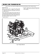
Wear a personal back support brace and use proper lift-
ing technique before lowering engine into vehicle. With a
person on each side of vehicle, install engine in reverse
order of removal replacing all lock nuts with new lock
nuts.
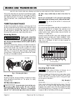
Whe
n installing air intake plenum to
carburetor, use ’roof and flashing’ poly-
urethane sealant to create a tight seal between the plenum and
carburetor intake. Use caution not to permit excess sealant to
fall into the carburetor.
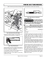
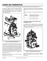
Tighten engine to subframe mounting hardware to 20 ft.
lbs. (30 Nm) torque (Ref Fig. 17 on page H-10).
Tighten drive clutch bolt to torque specified in CONTINU-
OUSLY VARIABLE TRANSMISSION section.
Install drive belt and CVT cover.
Tighten starter terminal nuts to specified torque.
If choke cable adjustment is required, adjust per FUEL
SYSTEM section.
Attach accelerator cable to governor per FUEL SYSTEM
section
Connect exhaust pipe to the engine and tighten clamp till
no loose play is present.
Check oil level in engine and adjust as needed.
Reconnect negative (-) battery cable and tighten hard-
ware to 5 ft. lbs. (7 Nm).
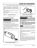
STARTER REPLACEMENT
To prevent the possibili-
ty of personal injury, dis-
connect the negative (-)
battery cable before starter removal.
Disconnect negative (-) cable from battery to prevent
electrical shorts that could cause an explosion.
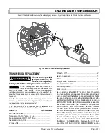
Remove engine (Ref Engine Removal). Follow proce-
dure to remove/install starter as outlined in the HONDA
®
Repair Manual for V-Twin Overhead Valve engine.
Reconnect negative (-) battery cables and tighten hard-
ware to 5 ft. lbs. (7 Nm).
MUFFLER REPLACEMENT
To prevent burns, check
that muffler has cooled
before replacing.
Tool list
Qty. Required
Torque wrench, 3/8" drive, ft. lbs ................................. 1
Ratchet, 3/8" drive ....................................................... 1
Socket, 3/4" ................................................................. 1
Wrench, 3/4"................................................................ 1
Needle nose locking pliers .......................................... 1
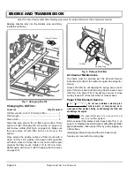
Release the handle and raise the truck bed.
Early production models were fitted with a heat
shield mounted to the underside of the truck
bed. There is no need to remove this heat shield.
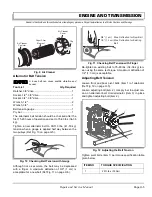
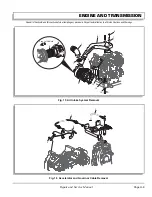
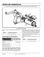
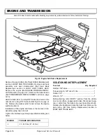
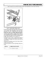
Remove the heat shield. Remove the spring (item 1)
using needle nose locking pliers (Ref Fig. 18 on page H-
12). Hold the bolt (item 2) using 3/4" socket and remove
the nut (item 3) using 3/4" wrench. Remove the washer
(item 4) and remove the muffler (item 5) from the frame.
Installation of muffler is the reverse of disassembly using
new lock nut.
!
!
!
!
!
!
Summary of Contents for ST 4X4
Page 6: ...Page iv Repair and Service Manual TABLE OF CONTENTS Notes...
Page 10: ...Repair and Service Manual SAFETY INFORMATION Page viii Notes...
Page 12: ...GENERAL INFORMATION ROUTINE MAINTENANCE Page A ii Repair and Service Manual Notes...
Page 24: ...SAFETY Page B ii Repair and Service Manual Notes...
Page 34: ...BODY AND TRUCKBED Page C ii Repair and Service Manual Notes...
Page 50: ...BRAKES Page D ii Repair and Service Manual Notes...
Page 68: ...CONTINUOUSLY VARIABLE TRANSMISSION CVT Page E ii Repair and Service Manual Notes...
Page 74: ...DIRECTION AND DRIVE SELECTOR Page F ii Repair and Service Manual Notes...
Page 80: ...ELECTRICAL Page G ii Repair and Service Manual Notes...
Page 114: ...FRONT SUSPENSION AND STEERING Page J ii Repair and Service Manual Notes...
Page 128: ...FUEL SYSTEM Page K ii Repair and Service Manual Notes...
Page 136: ...PAINT Page L ii Repair and Service Manual Notes...
Page 142: ...REAR AXLE AND SUSPENSION Page M ii Repair and Service Manual Notes...
Page 152: ...SPEED CONTROL Page N ii Repair and Service Manual Notes...
Page 160: ...TROUBLESHOOTING Page P ii Repair and Service Manual Notes...
Page 168: ...WHEELS AND TIRES Page R ii Repair and Service Manual Notes...
Page 174: ...GENERAL SPECIFICATIONS Page S ii Repair and Service Manual Notes...
Page 180: ...LIMITED WARRANTY Page T ii Repair and Service Manual Notes...
Page 182: ...Page T 2 Repair and Service Manual LIMITED WARRANTY Notes...


