C12 Maintenance 9. Joint #5
600
C Series Maintenance Manual Rev.2
Drive boss and the motor shaft:
Hexagon socket set screws: 2-M4×4
Tightening torque: 2.5
±
0.2 N·m
Align the screws to the two flat faces of the motor shaft and fix them.
Drive boss and the pulley 1:
Hexagon socket set screws: 2-M4×4 (with a brass bushing)
Tightening torque: 2.5
±
0.2 N·m
Fix the set screws while pressing the pulley 1 to the drive boss.
The brass bushing is not necessary for the screw for the flat surface (D-cut). Set the bushing to the other
screw and then fix the screw.
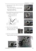
4.
Put the Joint #5 motor unit inside the Arm #4.
Pass the cables of the Joint #5 motor unit to the Joint #6 motor unit
side so that the cables can be stored in the storage space.
(See the photo)
5.
Pass the timing belt around the pulley 1 and pulley 2 and fix it
temporarily.
Make sure that the teeth of the timing belt engage with these of the
pulley.
As a rough guide of temporary fixing, check that the motor unit can
be moved by hand, and it does not tilt when being pulled. If the
belt is too loose or too tight, it will not have proper tension
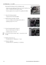
6.
Apply tension to the Joint #5 timing belt and fix the Joint #5 motor
unit.
Joint #5 Timing belt tension: 15 to 30 N
Bet tension meter setting value
Weight: 2.5 g/mm width × m span, Width: 6 mm, Span: 117 mm
Hexagon socket head cap bolts: 2-M4×15 (with a plain washer)
Tightening torque: 4.0
±
0.2 N·m
Regarding belt tension:
-
Jumping (position gap) may occur if the value is below the lower
limit.
-
Vibration (abnormal noise) or reduction in life of the parts may
occur if the value exceeds the upper limit.
-
When you replace with a new belt, belt extends and the belt tension
may decrease in the initial stage. Make sure to operate the robot
two to three days and check the belt tension again.
NOTE
Summary of Contents for C Series
Page 1: ...Rev 2 EM221R5039F 6 Axis Robots C series Maintenance Manual ...
Page 2: ...Manipulator manual C4 series Maintenance Manual Rev 2 ...
Page 20: ...Table of Contents xviii C Series Maintenance Manual Rev 2 ...
Page 22: ......
Page 69: ...C4 Maintenance 4 Cable Unit C Series Maintenance Manual Rev 2 49 ...
Page 70: ...C4 Maintenance 4 Cable Unit 50 C Series Maintenance Manual Rev 2 ...
Page 72: ...C4 Maintenance 4 Cable Unit 52 C Series Maintenance Manual Rev 2 ...
Page 73: ...C4 Maintenance 4 Cable Unit C Series Maintenance Manual Rev 2 53 ...
Page 74: ...C4 Maintenance 4 Cable Unit 54 C Series Maintenance Manual Rev 2 4 2 2 Power Cable ...
Page 75: ...C4 Maintenance 4 Cable Unit C Series Maintenance Manual Rev 2 55 ...
Page 196: ......
Page 283: ...C8 Maintenance 4 Cable Unit C Series Maintenance Manual Rev 2 263 ...
Page 284: ...C8 Maintenance 4 Cable Unit 264 C Series Maintenance Manual Rev 2 ...
Page 286: ...C8 Maintenance 4 Cable Unit 266 C Series Maintenance Manual Rev 2 C8 A1401 C8XL ...
Page 442: ...C8 Maintenance 18 C8 Option Parts List 422 C Series Maintenance Manual Rev 2 ...
Page 444: ......
Page 516: ...C12 Maintenance 4 Cable Unit 496 C Series Maintenance Manual Rev 2 ...
Page 517: ...C12 Maintenance 4 Cable Unit C Series Maintenance Manual Rev 2 497 ...
Page 518: ...C12 Maintenance 4 Cable Unit 498 C Series Maintenance Manual Rev 2 4 2 2 Power Cable ...
Page 519: ...C12 Maintenance 4 Cable Unit C Series Maintenance Manual Rev 2 499 ...


