4
4-2
Monitoring and Managing the Switch
Using the Hardware View
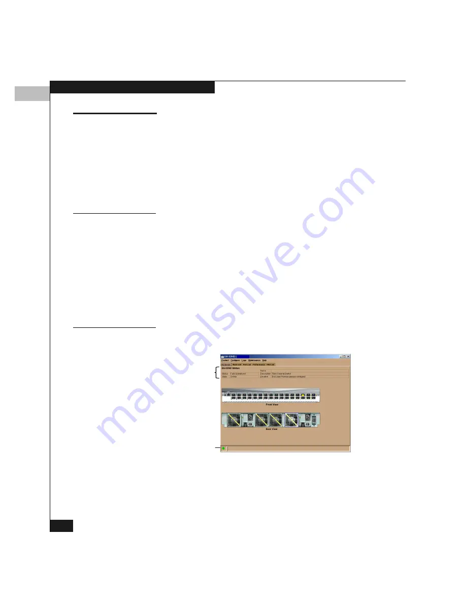
The Hardware view is the default view when you open the Product
Manager. Using this graphical view of the switch, you can view alert
symbols and simulated LEDs, display data, monitor status, and
obtain vital product information for the switch and its hardware
components.
To display the Hardware view from some other view in the Product
Manager, click the Hardware tab.
Identifying FRUs
Move the cursor over parts of the switch graphic in the Hardware
view to display pop-up labels identifying each hardware component
and its slot position in the chassis relative to identical components
installed in the switch.
FRUs include:
◆
Fan module — The DS-32M2 contains four fan modules.
◆
Power supply module — Note that each AC connector on the rear
of the unit is the location of an internal power supply.
◆
Ports (small form factor LC transceivers)
Monitoring Switch
Operation
This section describes the DS-32M2 Status table and status symbol
(shown below), which indicate the operating status of the switch:
Status Table
Status Symbol
ABC 123
ABC 123
Summary of Contents for Connectrix DS-32M2
Page 4: ...Connectrix DS 32M2 User Guide iv ...
Page 14: ...xiv Connectrix DS 32M2 User Guide Figures ...
Page 16: ...Connectrix DS 32M2 User Guide Tables xvi ...
Page 24: ...xxiv Connectrix DS 32M2 User Guide Warnings and Cautions ...
Page 42: ...1 1 18 Connectrix DS 32M2 User Guide Switch Operating Features ...
Page 72: ...3 3 24 Connectrix DS 32M2 User Guide Product Manager Overview ...
Page 226: ...B B 8 Connectrix DS 32M2 User Guide Configuring Network Addresses ...
Page 248: ...C C 22 Connectrix DS 32M2 User Guide Configuring the Switch from a Web Server ...
Page 332: ...F F 8 Connectrix DS 32M2 User Guide Customer Support ...
Page 351: ...Connectrix DS 32M2 User Guide g 19 Glossary ...
Page 352: ...g 20 Connectrix DS 32M2 User Guide Glossary ...


