6
Instruction Manual IM02602008E - Rev. D
Transformer Temperature Controllers
IM02602008E - Rev. D May 2019 www.eaton.com
2.2 Barrier Cabinet Version
WARNING
TURN OFF AND LOCK OUT THE POWER SUPPLY
BEFORE WORKING IN ANY ELECTRICAL OR
TRANSFORMER CABINET. FAILURE TO DO SO COULD
RESULT IN INJURY OR DEATH FROM ELECTRICAL
SHOCK.
Prepare the transformer cabinet for mounting the TC barrier
cabinet version, as follows:
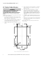
1. Cut a hole in the transformer cabinet to receive the TC
Barrier Cabinet. See Figure 7, TC Barrier Cabinet Cutout
and Drill Dimensions, for dimensions.
2. Drill six holes in the transformer cabinet to mount the
TC barrier cabinet. See Figure 7, TC - Barrier Cabinet
Cutout and Drill Dimensions, for dimensions.
3. Open
the hinged panel on the TC to expose the barrier
cabinet.
4. Remove
knock-outs in the barrier cabinet, as required,
and install cable clamps or grommets to secure and
protect the wiring.
5. Feed wiring into the barrier cabinet as it is being
installed. This includes wiring for the four thermo-
couples, two fans, external alarm (if provided), control-
ler power supply, 4-20mA output wiring and RS-485
cable for Modbus. Feed wires through the clamps and/
or grommet protected holes created by removing the
knock-outs.
6. Install the
TC barrier cabinet into the hole cut into the
transformer cabinet. Pull the wires into the barrier cabi-
net.
7. Secure the TC barrier cabinet to the transformer cabinet
with the six screws provided. Draw them snug but do
not overtighten them.
The TC
is now ready to be wired from outside the trans-
former housing.
Figure 7, TC Barrier Cabinet Cutout and Drill Dimensions

