5
Instruction Manual IM02602008E - Rev. D
Transformer Temperature Controllers
IM02602008E - Rev. D May 2019 www.eaton.com
1.6.3 TC Controller Unit
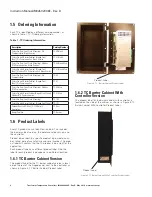
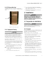
The product label for the TC controller is located on the
controller itself, as shown in Figure 6, TC Controller Product
Label.
Figure 6, TC Controller Product Label
1.6.4 Equipment Testing
CAUTION
NEVER PERFORM DIELECTRIC, MEGGER OR HIGH-
POTENTIAL TESTING ON TRANSFORMERS WHILE A TC
CONTROLLER UNIT IS CONNECTED. SUCH TESTING
MAY CAUSE INTERNAL DAMAGE TO THE CONTROLLER.
DISCONNECT THE TC CONTROLLER UNIT BEFORE
CONDUCTING DIELECTRIC, MEGGER, OR HI-POT TESTS..
Every Eaton TC model is tested at the factory. There is no
need for further testing of the TC.
If you prefer to test the transformer being monitored by the
TC, by performing dielectric, megger or hi-potential tests,
the TC controller unit must be disconnected before testing
to avoid damaging it.
Follow this procedure to disconnect the TC controller unit:
1. Disconnect the incoming power to the transformer
being monitored by the TC.
otee:
N
Wiring for the power input must be 12-22 AWG.
Fusing at the source should be appropriate for the
selected wire.
2. Lock out and Tagout the disconnected circuit.
Product Label
3. Access the controller by opening the hinged panel
(barrier cabinet version) or from within the transformer
cabinet (bezel-mounted version).
4. Disconnect the wiring to the controller. See Section
2.4, Wiring the TC, for locations.
2. Installation
WARNING
INSTALLING A TC TRANSFORMER TEMPERATURE
CONTROLLER THAT IS IMPROPERLY RATED FOR THE
ELECTRICAL SYSTEM VOLTAGE COULD CREATE A
POTENTIALLY HAZARDOUS CONDITION, RESULTING IN
INJURY OR EQUIPMENT DAMAGE.
2.1 Preparation for Installation
CAUTION
EATON TC PRODUCTS MUST BE INSTALLED OR
REPLACED BY A QUALIFIED ELECTRICIAN TO AVOID
INJURY OR EQUIPMENT DAMAGE.
2.1.1 General
Installation preparation is the same for both the barrier cabi-
net version and the bezel-mounted version. There are slight
differences in the mounting procedures.
Before installing an Eaton TC, do the following:
•
Verify that the area is clear of any dirt, debris, or clutter
that may hamper the installation process.
•
Verify that there is enough space in the transformer
cabinet to install and wire the TC unit. See Section 8,
Specifications, for dimensions.
•
Confirm that all tools and equipment needed for the
installation are available.
•
Confirm that output wiring from the four thermocouples
is long enough to reach the installed TC unit.
•
Confirm that the incoming power source for the TC unit
is available, as 100 to 240 Vac, and that the wires are
long enough to reach the installed TC unit. Wiring for the
power supply must be 12 to 22 AWG, and fitted with a
fuse at the end appropriate for the selected wire.
•
Confirm that 4-20mA output wiring is long enough to
reach the TC controller component.
•
Confirm that the Modbus RS485 cable is long enough to
reach the TC unit.
•
Confirm that external alarm indicators, trip actuators, dis-
crete input devices, and/or SCADA systems are installed.

