71
Instruction Manual IM02602008E - Rev. D
Transformer Temperature Controllers
IM02602008E - Rev. D May 2019 www.eaton.com
4.3 Remote Operation
Operating the TC-50 Modbus and TC-100 models remotely
requires a standard Modbus communications network.
This arrangement allows the user to monitor current oper-
ating conditions of the transformer and controller, such as
winding temperatures, active alarms, and status of the fan,
alarm, and trip relays. It also allows the user to monitor
ongoing statistics for the winding temperatures and fans as
well as download alarm and trip event logs and trend data.
Finally, the user can make configuration changes which can
be useful, for example, to change the trend data logging
interval to troubleshoot possible problems.
4.3.1 Introduction
The TC-50 Modbus and TC-100 models communicate over
an RS-485 network using standard Modbus RTU protocol.
A 4-pin connector is provided for wiring to the RS-485
network. TX and RX LEDs illuminate when when data is
transmitted or received, aiding in network troubleshooting.
Communications settings for baud rate, parity, number of
stop bits, and Modbus address are programmable through
the front panel keypad or via the USB interface to a local
computer running the TC-50 Modbus and TC-100 PC soft-
ware.
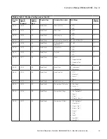
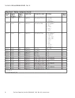
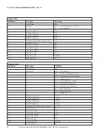
A register map detailing available data can be found in
Appendix C-Modbus Registers.
4.3.2 Features
The TC-50 Modbus and TC-100 models have the following
features:
•
A means of communicating using the standard Modbus
RTU protocol over an RS-485 network connection.
•
Supports baud rates of 9600, 19200, and 38400, select-
able via the front panel keypad for networking flexibility.
•
Selectable addresses 1-247 via the front panel keypad.
•
Data in fixed-point formats.
•
RS-485 TX/RX indicators.
•
Termination resistor is dip-switch selectable.
4.3.3 Hardware Installation
4.3.3.1 Simplified Wiring Rules
The TC-50 Modbus and TC-100 models provide a half-duplex,
EIA/RS-485 network connection. EIA/RS-485 is a multi-drop,
industrial-grade communications standard.
It is a “balanced differential” signal that feeds over a twist-
ed-pair containing A and B signals and a common. For this
reason, it is very important to carry all three conductors to
ensure a high quality communications network.
4.3.3.2 Signal Polarity
The data is considered a binary 1 when the voltage level of
the
A
signal is less than the voltage level of the
B
signal. A
binary 1 is considered a Mark or Off whereas a binary 0 is a
Space or On.
4.3.3.3 Cabling
The recommended cable for maximum performance of the
RS-485 network is a twisted pair with 22-AWG stranded 7
x 30 conductors with PVC insulation under aluminum foil
polyester tape, a single 24-AWG stranded 7 x 32 conductor
with PVC insulation and aluminum foil polyester tape, and an
all-over braided shield (Belden 3106A). Cables with similar
shielding and smaller wire sizes (24-AWG) can be used for
easier wiring. The cable characteristic impedance should be
120 ohms.
4.3.3.4 RS-485 Bus Termination
Assuming the characteristic impedance of the cable is 120
ohms, each segment of the RS-485 network should be ter-
minated with an end-of-line terminating resistor. A resistor
value of 120 ohm should be used at the Master end of the
network as well as at the end of the line. This terminating
resistor is mounted at the factory and can be switched in
by changing the SW1 on (
1
). SW1 is set to the
Off
position.
SW1 and SW4 are set to the
Off
position at the factory, and
in most installations, the SW1 terminating resistor does not
need to be set to the
On
position.
4.3.4
Connectors
4.3.4.1
RS-485 Connector
Figure 14, Modbus Board Wiriing, shows a typical Modbus
network where the TV-50 Modbus or TC-100 (slave) and host
devices are connected to the RS-485 Modbus Master..
TC-50 Modbus
or
TC-100
A
B
COM
Shield
A
B
COM
Shield
A
B
COM
Shield
Modbus
Master
*
SEE WIRING NOTES FOR CHASSIS GND CONNECTION
EIA/RS-485
TERMINATE
TC-50 Modbus
or
TC-100
TC-50 Modbus
or
TC-100
Figure 14, Modbus Board Wiring


