1
Instruction Manual IM02602008E - Rev. D
Transformer Temperature Controllers
IM02602008E - Rev. D May 2019 www.eaton.com
1. Introduction
The content of this manual is organized into seven sec-
tions, and three appendixes, as follows:
•
Introduction
•
Installation
•
Operating Functions
•
Operating Procedures
•
Maintenance and Repair
•
Troubleshooting
•
Specifications
•
Appendix A - Programming Quick Reference Guide
•
Appendix B - Modbus Registers
1.1 Product Overview
Eaton
®
Transformer Temperature Controllers monitor the
temperature of up to three ventilated, dry-type transformer
windings. They also monitor the ambient temperature with-
in the cabinet in which the transformer is installed.
These temperatures are detected by thermocouples placed
within the transformer windings and inside the cabinet.
If winding temperatures exceed a preset limit (setpoint)
relays are tripped to start cooling fans to reduce tempera-
tures and prevent equipment damage. If higher trip and
alarm winding temperature setpoints are reached, Form C
contacts may be used to trip a remote alarm and ultimately
trip the transformer offline.
Three models of the transformer temperature controller
(TC) are available; the
TC-50
, the
TC-50
Modbus
, and the
TC-100
. The TC-100 includes Modbus and has advanced
features for discrete inputs, monitoring, and data logging.
All models have a common appearance but vary in function-
ality. The functionality described in Section 4.1.2 -Operating
the TC Manually, and Section 4.2 -Local Operation, apply to
all models unless otherwise noted in a heading or the text.
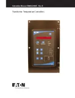
All TC models have a front panel that provides a communi-
cations interface between the controller and an operator.
The panel consists of an 9-character LED display, 9 discrete
LEDs, and 9 pushbuttons. Communication is also possible
using a laptop computer connected to a front USB port, or
through Modbus (on the TC-50 Modbus, and the TC-100
models
A sealed controller unit processes all data received.
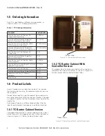
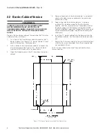
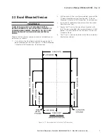
All TC models are available in two versions: a barrier cabi-
net version (Section 1.2) or a flush, bezel-mounted version
(Section 1.3).
The features of each model are described below.
All models
(TC-50, TC-50 Modbus, and TC-100)
have these
standard features:
•
Operates on 100 to 240 Vac, 50 or 60 Hz power.
•
LED display shows conditions and values
•
Panel LEDs indicate system status.
•
Cooling fans turn on automatically when temperatures
exceed a setpoint, or a trip relay shuts down the trans-
former.
•
Setpoints can be used to turn on either fan, or turn on an
Alarm or Trip relay for a high temperature condition.
•
Alarm and trip relays can function as fail-safe relays (nor-
mally energized when the TC is powered up).
•
Alarm buzzer sounds but can be silenced without cancel-
ing the alarm.
•
Certifications include Underwriter’s Laboratories (UL
®
), to
Standard 873, CSA C22.2 No. 24-93.
•
Provides 4-20 mA analog signal for remote indication or
use with SCADA systems.
•
Unit can be used for single-phase transformers, or other
devices, by selecting or deselecting individual elements.
•
Fans can be operated automatically for short periods to
prevent motor seizing.
The
TC-50 Modbus
model has all of the standard features,
plus:
•
RS-485 connection for Modbus communications.
The
TC-100
model has all of the standard features, plus
these additional features:
•
RS-485 connection for Modbus communications.
•
Monitors two discrete inputs, such as opening or closing
fan louvers or doors.
•
Provides automatic monitoring and logging functions, and
temperature trending, to analyze operation and achieve
faster restoration.

