2
Instruction Manual IM02602008E - Rev. D
Transformer Temperature Controllers
IM02602008E - Rev. D May 2019 www.eaton.com
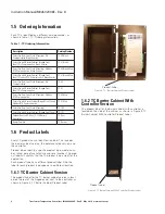
1.2 Barrier Cabinet Version
The barrier cabinet version of the TC models has three
major components: the barrier cabinet, the controller and
a hinged panel, as shown in Figure 1, TC Barrier Cabinet
Version.
Figure 1, TC Barrier Cabinet Version
With the barrier cabinet version, the barrier cabinet recess-
es into a cutout in the transformer cabinet at the time of
installation. This provides a barrier that prevents user expo-
sure to high voltages inside the transformer cabinet while
the TC is being installed, wired or serviced.
The controller unit mounts to the back of the hinged panel.
With the hinged panel open, terminal points on the control-
ler are readily available for wiring the unit. The barrier cabi-
net prevents any physical entry into the transformer cabinet.
Once wired, the controller performs the monitoring, pro-
gramming, reporting and testing functions. When the
hinged panel is closed, the controller moves back into the
barrier cabinet and the front panel (mounted to the door of
the enclosure) is exposed.
The front panel of the TC is shown in Figure 2, TC Front
Panel. This front panel provides the user interface to moni-
tor, program, and report the TC functions.
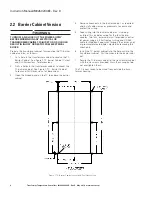
The barrier cabinet version mounts with 6 screws.
Removing the three screws opposite the hinges allows the
hinged panel to open and expose the controller unit and the
inside the barrier cabinet,
Controller
Barrier Cabinet
Hinged Panel
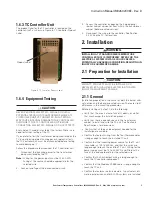
Figure 2, TC - Front Panel
1.3 Bezel-Mounted Version
The bezel mounted version of the TC mounts flush against
the transformer cabinet.
The controller unit is attached to the rear of the front panel,
and recesses into a hole cut into the cabinet prior to installa-
tion. Following installation, the bezel around the front panel
sets securely against the cabinet, as shown in Figure 3, TC
Bezel-Mounted Version.
Once wired, the controller performs the monitoring,
programming, reporting and testing functions of the TC.
However, accessing the bezel-mounted controller, to wire it
or replace fan fuses, requires working inside the transform-
er cabinet. This exposes the installer to any high voltages
that may be present inside the cabinet.
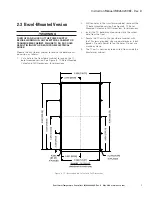
The bezel-mounted version is mounts from within the trans-
former cabinet with 10 screws.

