Continued
Cable Connections
The
iQ
Servo Presses are configured in one of two ways,
depending on the model.
E
ach has unique cabling require-
ments.
Version 1- Remote Controller
Configuration
(Press Models: 43S215, 43S245-AX)
Typical Components:
•
iQ
Generator
• iQ
Servo Press
•
Remote Controller (contains servo electronics)
•
HMI Interface (optional on some systems)
•
Customer Automation Equipment
Connect the Cables
Use the following references as guides to making the
connections:
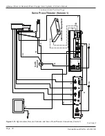
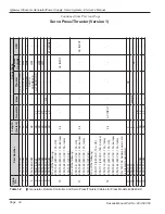
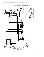
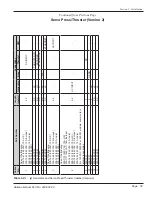
For press model 43S215, use Figure 3-13 and Table
3-IV.
For press models 43S245-AX, use Figure 3-13 and
Table 3-V.
1. Make the basic cable connections
1
through
9
, and
13-16
.
2. Make any optional connections.
3. Connect any customer-supplied equipment such as
automation. Use cables
17
and
18
for automation.
4. Connect customer-supplied electricity using cables
10
,
11
, and
12
.
Connect the power cords last, but do not turn on the
power yet.
5. Recheck all connections. When they are secure, you
are ready to connect electrical power.
6. Finally, connect electrical power. See
Section 11,
Specifications
for AC power requirements.
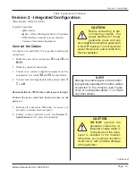
Before connecting or
disconnecting cables:
Put power switches for
the
iQ
generator, press,
remote controller, and any user-
supplied automation equipment in
the OFF position. Turn off electrical
power. Remove AC power cords
from their receptacles.
CAUTION
DO NOT
operate the
generator unless the
ultrasound coaxial ca-
ble is connected and
the transducer is installed in the
thruster. Otherwise, an overload
condition could occur, with pos-
sible damage to the generator.
CAUTION
NOTE
Some connectors have a pair of
threaded jack screws to secure the
connector. Make sure the screws are
snug, but do not overtighten them.
Page 29
Dukane Manual Part No. 403-587-00
Section 3 - Installation

