Installation Instructions for Wi-Q Technology™ EXQ Exit Hardware Trim
BEST
a Product Group of dormakaba USA Inc.
14
Installing the exit hardware and trim
13
Route sensor wires
Use the following table to determine sensing wire
functions:
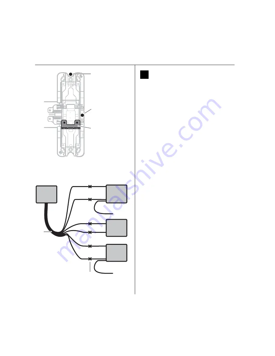
1 Pull wires from the sensor harness, door position
switch, latchbolt switch, and touchbar switch to the
top of the device head as shown in Figure 23.
Note:
For Precision 2300, Sargent 8800, or any Von
Duprin application without RQE, pull the door position
switch and sensor harness wires into the battery bracket
area rather than the device head.
Note:
For Von Duprin applications with RQE, touchbar
switch wires must be re-routed into the device head in
such a way as to avoid any pinching or contact with
moving parts. The sensor harness can be routed into the
head area through any suitable hole in the chassis.
2 Cut the wires to the appropriate length (that is,
remove the excess to leave minimal slack after the
spliced connections).
3 Strip the wire ends for connection using the butt-
splices.
4 Make wire connections as detailed in Figure 24 or Fig-
ure 25 using the butt-splices (provided).
Note:
For Sargent devices, connect the door position
switch to the two white sensor harness wires.
Note:
In the case of unused wires, be sure to cover the
ends with electrical tape.
Wire function
Colors
No. of
wires
Touchbar monitoring (RQE)
Orange and tan
2
Door sensing
White
2
Latchbolt sensing
Red and blue
2
Figure 23 Pulling sensor harnesses to the top of the
device head
Pull sensor
wires to top of
device head
(shaded area)
Wire entry from
trim for vertical
rod (2200, 2700,
2800) device
Wire entry from
trim for rim
(2100) device
Red
Violet
NO
Blue
Blue
COM
Wht
Wht
Red
NC
Not used
Wht
Wht
Org
Org
NC
Tan
Tan
COM
Latchbolt
switch
EXQ Trim
Door
position
switch
Touchbar
switch
Yellow
NO
Not used
Figure 24 Schematic diagram for connecting Precision
sensor harness wires
Sensor
harness
Butt
splices
NO
= Normally Open
NC
= Normally Closed
COM
= Common
Installation Instructions for Wi-Q Technology™ EXQ Exit Hardware Trim
BEST
a Product Group of dormakaba USA Inc.
13
Installation Instructions for Wi-Q Technology™ EXQ Exit Hardware Trim
Installing the exit hardware and trim
For mortise exit device installations
(mortise cylinder)
1
For doors less than 2
″
in thickness
, place the cylin-
der ring provided on the cylinder.
2 Rotate the cylinder cam to the 12 o’clock position, as
shown in Figure 21.
3 Using a cylinder wrench (ED211), insert the cylinder
through the cylinder opening in the escutcheon and
screw the cylinder into the mortise case. Make sure
that the figure-8 hole is in the 12 o’clock position.
Caution:
Do not screw the cylinder in too tightly.
Doing so may cause users to be locked out.
12
Install exit hardware and
secure escutcheon
For Precision 2200, 2700 and 2800 exit devices only
■
Drill a 5/16” hole through the front part of the chassis
as shown in Figure 22. (This hole is used to pass the
sensor harness and door position switch wires into the
chassis area.)
For all exit devices
1 Make any adjustments to the exit hardware necessary
for compatibility with lever function outside trim.
2 Install the exit hardware (lock stile case, touch bar
assembly, latches and rods [if applicable], and related
hardware); follow the instructions provided by the exit
hardware manufacturer.
Note:
The escutcheon is secured on the outside of the
door by the screws used to mount the lock stile case on
the inside of the door.
Caution:
When securing the escutcheon, make
sure that it does not pinch any wires.
Figure 20 Rim cylinder components
Rim
cylinder
Screws
Spindle
Clamp plate
Orient the curve
toward the cylinder.
Figure 21 Mortise cylinder components
Mortise cylinder
Cam in 12 o’clock
position
View of the back
of the cylinder
Figure 22 Drilling 5/16” hole for Precision 2200, 2700,
and 2800 exit devices only
Drill 5/16”
hole thru the
face of the
chassis here.
Drill ONLY
for 2200,
2700 and
2800 devices
Summary of Contents for BEST Wi-Q ONGUARD
Page 7: ...A Glossary Glossary 109 B Lock Installation Lock Installation 113 ...
Page 40: ...40 2 Select Inbound Rules Figure 13 Inbound Rules Select Inbound Rules ...
Page 45: ...45 7 De select the Public option Click Next Figure 18 De select Public ...
Page 52: ...52 Figure 27 Wi Q Interface Setup Wizard Click Next ...
Page 57: ...57 Figure 33 Custom Setup Options Click Next ...
Page 75: ...75 To add a new Sign On Credential 1 Select Add Figure 52 Add Segment Sign On Credential 1 ...
Page 113: ...B Lock installation ...


