84
85
E
n
g
li
sh
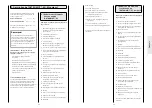
6.4.2 Reconiguration of the
ARTROMOT®-E2 compact
The ARTROMOT®-E2 compact can be used
on the left and on the right elbow joint.
however, the device must be converted
irst. This is done very quickly.
1. Activate the “transport setting” function
in the menu (see also 5.3) and
start the ARTROMOT®-E2 compact.
2. Release the wheel brakes (22) and roll
the ARTROMOT®-E2 compact to the
side of the elbow to be treated.
3. Pull the pin for the swiveling movement
of the upper arm support (5) downward
and swing the support 180° towards the
inside.
Attention: Release the pin (5) while the
support is swinging; you will hear it lock
into place on the other side (see conver-
sion diagram
1
a).
4. Open the locking screw for the swiveling
movement of the forearm support (6)
and swing the support with motor b
180°.
Tighten locking screw (6) (see conver-
sion diagram
1
b).
5. Open the locking screw for right/left
positioning (7) two revolutions. Move
the forearm support to the lower recess
in the slot and turn it 180° in this posi-
tion. Then move the forearm support
back to the middle position (setting 0)
and tighten locking screw (7) again (see
conversion diagram
2
c).
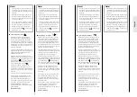
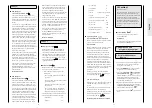
Conversion diagram ARTROMOT®-E2 compact:
a
b
c
1
2
6.4 Conversion
Note!
On the display the respective sides are
indicated as follows:
–
The CPM device (upper arm sup-
port) is prepared for the left elbow.
–
The CPM device (upper arm sup -
port) is pre pared for the right elbow.
–
This symbol appears during con-
version of the CPM device.
6.4.1 Reconiguration of the
ARTROMOT®-E2
The ARTROMOT®-E2 can be used on the
left and on the right elbow joint. however,
the device must be converted irst. This is
done very quickly.
1. Activate the “transport setting” function
in the menu (see also 5.3) and
start the ARTROMOT®-E2.
2. Adjust an angle of 90° for horizontal ad-
duction/abduction (indexing knob 1) (see
conversion drawing
1
).
3. Open locking screw (4) for the height
adjustment, remove the armrest for the
healthy arm and place it on the seat (see
conversion diagram
1
).
4. hold the double joint (3) of the motion
element and open the locking screw
for height adjustment (4) on this side as
well.
5. Remove the motion element and insert
it on the opposite side. Tighten the lock-
ing screw (4).
(see conversion diagram
1
b, c).
6. Pull the pin for the swiveling movement
of the upper arm support (11) downward
and swing the support 180° towards the
inside.
Attention: Release the pin (11) while the
support is swinging; you will hear it lock
into place on the other side (see conver-
sion diagram
2
d)
7. Open the locking screw for the swiveling
movement of the forearm support (12)
and swing the support with motor b
180°. Tighten locking screw (12) (see
conversion diagram
2
e).
8. Open the locking screw for right/left
positioning (13) two revolutions. Move
the forearm support to the lower recess
in the slot and turn it 180° in this posi-
tion. Then move the forearm support
back to the middle position (setting 0)
and tighten locking screw (13) again (see
conversion diagram
3
f).
Conversion diagram ARTROMOT®-E2:
1
2
3
Summary of Contents for ARTROMOT-E2 COMPACT
Page 1: ......
Page 4: ...iV Abbildungen ARTROMOT E2 Figures Illustrations Ilustraciones Illustrazioni A B C D E F ...
Page 149: ...288 ...
Page 153: ......


