17
SAFETY SIGN LOCATION
IMPORTANT: Decals must be kept clean to allow easy reading at all times.
Manual
No
. F4117E987E V1.1
Page 1: ...Operator s Manual Forage Harvester Manual No F4117E987E V1 1 ...
Page 2: ...e or representative of Dion Ag Inc has the authority to amend or modify in any manner whatsoever the terms of the present warranty The express warranties herein contained exclude all other express implied or statutory warranties THIS WARRANTY IS IN LIEU OF ALL OTHER WAR RANTIES INCLUDING THE WARRANTIES OF MERCHANTABILITY AND OR FITNESS FOR ANY PARTICULAR PURPOSE Right to Inspect Dion Ag and its au...
Page 3: ...luable tool for operating and maintaining this fine ma chine Use this manual as your guide Practicing the instructions given here will result in many years of dependable service from your machine Your dealer can give you assistance with parts and specially trained personnel to assist you in repair and maintenance Call your dealer if you need any assistance or information Manual No F4117E987E V1 1 ...
Page 4: ...CONNECTING THE POWER TAKE OFF PTO 26 INSTALLING THE FOLDABLE SPOUT F41 MODEL ONLY 27 INSTALLING THE 12 30 cm SPOUT EXTENSION F41 MODEL ONLY FIGURE 12 28 INSTALLING THE 24 60 CM SPOUT EXTENSION F41 MODEL ONLY 29 HOW TO MAKE THE ELECTRICAL CONNECTIONS ON THE SPOUT F41 MODEL ONLY 31 INSTALLING THE CLOSING PLATE ON THE SPOUT 32 INSTALLING MUDGUARDS OVER TANDEM WHEELS 32 INSTALLING AN ATTACHMENT ON THE...
Page 5: ...INE DETECTS A FERROUS METAL 97 WHAT TO DO IF MATERIAL ACCUMULATION OCCURS CLOGGING 98 HOW TO BY PASS THE METAL DETECTOR 99 SHEAR BOLT 100 PRESSURE AND FLOW CHARTS FOR STANDARD NOZZLE 101 STANDARD NOZZLE FOR WATER SPRAYING TEEJET XR8004VS 101 HOW TO OPERATE THE LIQUID INCORPORATION SYSTEM 101 CALIBRATION PROCEDURES 101 PRESSURE ADJUSTMENT 101 DETECTION SYSTEM FOR SAFETY BOLT BREAKAGE OR FRICTION CL...
Page 6: ...CE PROCEDURE FOR THE CUTTER HEAD BOTTOM PLATE ASSEMBLY 141 MAINTENANCE PROCEDURE FOR THE FAN BOTTOM PLATE ASSEMBLY 142 CORN CRACKER SHEAVE ALIGNMENT 144 CORN CRACKER Q D BUSHINGS 155 CORN CRACKER LOWER ROLL BEARINGS 145 CORN CRACKER UPPER ROLL BEARINGS 147 CORN CRACKER LOWER ROLL HALF BOTTOM PLATE 149 CORN CRACKER ROLL SCRAPER 151 UPPER CORN CRACKER ROLL ZERO POSITION ADJUSTMENT 152 UPPER CRACKER ...
Page 7: ... Spout turning radius F41 Stinger 200 508 cm ANGLE DRIVE TRANSMISSION 540 or 1000 RPM buyer s choice MAIN TRANSMISSION 3 speed transmission with overload clutch 3 lengths of cut OPERATING CAPACITY 540 RPM to 730 RPM 90 to 135 HP 1000 RPM to 815 RPM 90 to 180 HP 1000 RPM to 1033 RPM 160 to 300 HP ELECTRICAL CONTROLS Transmission Spout 230 rotation Deflector CUTTER HEAD 12 helicoidal knives or 8 kni...
Page 8: ...ndard on F41 Stinger model Spout extension 12 or 24 30 or 60 cm F41 model only Single wheels or tandem wheels Double sprocket wheels for lengths of cut 17 teeth for 1 4 6 35 Deflector light Inspection light Manual cord quick disconnect hitch Electrical heavy duty quick disconnect hitch N A on F41 Stinger model Liquid incorporation system Extra tank for liquid incorporation system Recuperation grai...
Page 9: ...odel and the serial num bers when ordering parts or regarding any other correspondence referring to your machine Write down your number here MODEL NO SERIAL NUMBER SERIAL NUMBER LOCATION MADE IN CANADA DION AG INC BOISBRIAND QUE MODEL NO SERIAL NO Dion Ag Inc DFE MADE IN CANAD A D F E INC BOISB RIAND QUE MODEL NO SERIAL NO PAR BY REAR RIGHT LEFT FRONT Manual No F4117E987E V1 1 ...
Page 10: ... fluid levels Look for loose or missing bolts and parts Run the machine in a stationary position at half speed for a short period of time Shut off tractor engine Make sure all moving parts have stopped then inspect bearings for over heating excessive wear or loose flanges and lock collars Check metal detection system for proper operation if installed on machine Always service metal detector when t...
Page 11: ... machine according to the Servicing section Check tension of belts and chains Check all sheaves and sprockets for correct alignment Check tire pressure See Specifications Make sure harvester is hooked to tractor correctly and that the safety chain is safely installed Make sure all controls are operable Sharpen knives and adjust shearbar once or twice a day CHECK LIST Manual No F4117E987E V1 1 ...
Page 12: ...ut notice The Safety section of your Operator s manual is intend ed to point out some of the basic safety situations which may be encountered during the normal operation and maintenance of your Forage Harvester and to suggest possible ways of dealing with these situations This sec tion is NOT a replacement for other safety practices fea tured in other sections of this book WARRANTY INFORMATION The...
Page 13: ... For safe operation of a Forage Harvester you must be a quali fied and authorized operator To be qualified you must read and understand the written instructions supplied in this Operator s Manual have training and know the safety rules and regulations for the job Some regulations specify that no one under the age of 16 years for example may operate power machinery This includes trac tors It is you...
Page 14: ...justments while the machine or tractor engine is running Never attempt to check or adjust chains while the ma chine is running Make sure all rotating parts are stopped and the trac tor engine is turned off before cleaning the machine throat Never park the Forage Harvester in its transport posi tion Lower the attachment to the ground first Before starting the tractor engine make sure all guards shi...
Page 15: ...od condition Never step across any PTO driveline Never use the PTO driveline as a step Keep a good distance away from a rotating driveline approximately the distance equal to your height MANDATORY STOPPING PROCEDURE No matter what type of machine is being used it is ex tremely hazardous to perform any kind of maintenance work while the machine is running It could lead to seri ous injuries or even ...
Page 16: ...s the universal joints Item 3 The telescopic driveline which attaches to the tractor PTO is covered with a non rotating shield Item 4 An hinged guard covers the tool box the transmis sion shaft between the angle drive transmission and the cutting head the driving belts for the for ward neutral reverse transmission and the driving system for the feeding rolls and the attachments Item 5 An hinged gu...
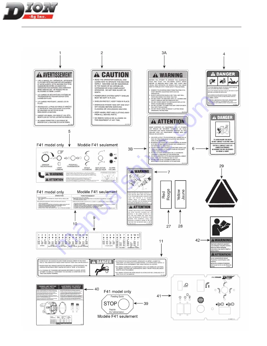
Page 17: ...17 SAFETY SIGN LOCATION IMPORTANT Decals must be kept clean to allow easy reading at all times Manual No F4117E987E V1 1 ...
Page 18: ...18 SAFETY SIGN LOCATION IMPORTANT Decals must be kept clean to allow easy reading at all times Manual No F4117E987E V1 1 ...
Page 19: ...ecals must be kept clean to allow easy reading at all times 3A 3B 17 11 42 1 16 16 23 15 4 4 4 16 28 27 4 30 31 22 2 17 18 18 6 18 28 27 29 16 1000 CAUTION AVERTISSEMENT FORCORNONLY POURMAÏSSEULEMENT F41 30 751P Manual No F4117E987E V1 1 ...
Page 20: ...20 SAFETY SIGN LOCATION 14 7 15 24 35 16 26 4 32 8 4 20 12 12 12 12 13 4 IMPORTANT Decals must be kept clean to allow easy reading at all times Manual No F4117E987E V1 1 ...
Page 21: ...ing paper and apply the decal in part and align its position as per the surrounding parts Slowly peel off the remaining backing paper and apply hand pressure 3 Press slightly on the surface of the safety sign to remove all air bubbles SAFETY SIGN LOCATION IMPORTANT Decals must be kept clean to allow easy reading at all times 16 16 25 39 41 42 10 5 Manual No F4117E987E V1 1 ...
Page 22: ...ntrol box 1 Control box bracket to be bolted inside tractor cab HARVESTERS ARE SHIPPED TO OPERATE AS FOLLOWS 540 or 1000 RPM Power Take Off PTO purchas er s choice Control box for the metal detector the deflector the spout and the transmission Length of cut 3 8 9 5 and 1 2 13 Recuter bar attachments factory installed All knife and shear bar adjustments are done at the factory Built in knife grinde...
Page 23: ...ing a grain pan and a front rubber pad assembly for corn crop if required Installing the corn cracker if required Installing a spout light option F41 model only Installing an inspection light option Installing the liquid incorporation system option PREPARING THE FORAGE HARVESTER According to the attachment being used the following procedure should be carried out on the Forage Harvest er please als...
Page 24: ... to the Forage Harvester using the quick connects item 4 5 Connect the power wire item 5 to the tractor bat tery To do so first disconnect the tractor s battery negative terminal to prevent any short circuit Must be bolted inside tractor cab Figure 3 Control box INSTALLING THE CONTROL BOX F41 STINGER MODEL ONLY FIGURE 4 AND FIGURE 5 On the F41 Stinger model a ball joint support item 7 is used for ...
Page 25: ...EMBLING INSTRUCTIONS TO FORAGE HARVESTER 2 5 Quick disconnect BLACK negative WHITE positive 3 4 6 4 To tractor Cable bracket TO TRACTOR BATTERY Figure 6 Control box wire connections Manual No F4117E987E V1 1 ...
Page 26: ...4 in Figure 6 and put back the cap item 6 on the connector item 3 CONNECTING THE POWER TAKE OFF PTO FIGURE 7 AND FIGURE 8 1 Couple PTO item 1 to the Forage Harvester with bolt item 2 and tighten well Connect both halves of the PTO together making sure to align the two special grooves for a correct yoke alignment 2 A pin placed between the two grooves allows you to align the crosses on the PTO in o...
Page 27: ...he spout later on 1 Figure 9 2 Raise up the spout as shown below 3 Position the cable support bracket item 4 as shown here 4 Figure 10 4 Secure the spout using the seven carriage bolts item 2 that were previously removed Tighten well 2 2 3 Figure 11 5 Tighten the two hexagonal head bolts item 3 that serve as a hinge ASSEMBLING INSTRUCTIONS Manual No F4117E987E V1 1 ...
Page 28: ...even carriage bolts item 2 3 Install the 12 30cm extension item 1 with the same seven 1 2 X 1 1 4 lg carriage bolts item 2 NOTE The spout and the extension rotate together when the spout assembly is rotating ASSEMBLING INSTRUCTIONS 2 2 3 1 Figure 12 Installation of the 12 30cm spout extension Manual No F4117E987E V1 1 ...
Page 29: ...g bolts and six 1 2 X 1 3 4 lg bolts are needed here to secure the extension 6 Grease the friction collar item 8 of the extension 7 Install the spout item 3 8 Install the retaining plates item 2 and shims item 4 supplied with the machine and adjust shim thick ness to allow free rotation 9 Install the rotation mechanism item 1 back in place 10 Install the two adjustable reinforcement rods Items 9 a...
Page 30: ...30 ASSEMBLING INSTRUCTIONS 2 4 7 1 8 6 10 11 11 9 3 Figure 14 Installation of the 24 60cm spout extension 2 carriage bolts 1 2 X 2 lg 2 bolts 1 2 X 2 lg Manual No F4117E987E V1 1 ...
Page 31: ...power cable of the deflector motor to the support bracket item 2 using a tie wrap 3 Connect the electrical cable item 3 to the deflector motor item 1 cable item 4 NOTE Make sure to leave sufficient electrical cable length allowing spout to turn freely NOTE The rotation motor is already connected 4 3 2 1 Figure 15 Connecting electrical cables on the spout Manual No F4117E987E V1 1 ...
Page 32: ...ing order and keep all bolts and nuts to reinstall these parts later on in step 3 1 2 Figure 17 2 Install the 2 60cm extension item 3 aligning it with the three existing holes and using three 3 8 X 3 4 lg flange bolts heads on the inside and three 3 8 flange nuts on each side 3 Figure 18 3 Reinstall the deflector item 1 and the spring plate item 2 on the extension item 3 Make sure de flector is mo...
Page 33: ... in place by two 1 2 X 1 1 4 lg bolts item 4 and two 1 2 nuts 2 Place a rubber spacer item 3 on each bracket item 2 and fasten the mudguard item 1 over the spacer and the brackets with six 5 16 X 1 lg carriage bolts and six nuts ASSEMBLING INSTRUCTIONS 1 2 2 3 3 4 5 4 Figure 20 Installing mudguards over tandem wheels Manual No F4117E987E V1 1 ...
Page 34: ...117for prop er balancing spring adjustments which vary ac cording to the type of attachment used 2 In the case of a 4 row corn attachment install the 1 1 4 lock pin item 4 with a safety lock supplied with the machine A 5 8 dia X 2 lg pin item 15 locks the hydraulic lifting cylinder in place and makes the installation of an attachment easier 3 Slowly move the Forage Harvester towards the attachment...
Page 35: ...the ground or ease the attachment hydraulic lifting to avoid pos sible obstacles in the field Refer to page 117 for balancing spring adjustment 7 Install the Corn Row Crop attachment drive roller chain item 16 use the 80 X 35 lg chain with one 80 connecting link 8 Install the Hay Pick up attachment drive roller chain item 17 Use 80 X 35 lg chains with one 80 con necting link and one 80 link those ...
Page 36: ... CORN CROP FIGURE 24 1 When the corn cobs are very dry which leads to grain lost under the feed rolls install the grain pan item 1 as shown 2 Tighten the four holders item 2 with four 3 8 X 3 4 Lg carriage bolts item 8 and four flange nuts do not tighten The heads of the bolts must be on the inside as shown on the illustration 3 With four 3 8 X 3 4 Lg flange bolts item 3 in the frame holes item 4 ...
Page 37: ...h terminal item 7 and to the box terminal item 8 Close the box cover and turn the toggle switch OFF 4 Bring the wire item 9 down and run it through the hole item 10 Then connect it to the plug item 11 located underneath the guard and above the sheave 5 Bolt the light support bracket item 12 using the two existing bolts item 13 of the spring support Secure the light assembly item 14 to the support ...
Page 38: ... and on the box terminal item 8 4 Close up the box and leave the toggle switch to OFF 5 Connect the plug item 9 of the wire item 10 of the inspection light item 11 with already mounted wire item 17 If the Forage Harvester is equipped with the spout light use the supplied Y shape plugs item 12 6 Bring the wire along the side of the spout and secure it with nylon tie wraps 7 Bring the wire and run i...
Page 39: ...and 1a with two arms item 2 four 1 2 x 6 1 2 lg carriage bolts and four 1 2 lock nuts Position the rear support bracket item 1a against the exterior shaft reinforcement plate item 5 1 1a 5 2 4 3 5 1a Figure 27 Installing the tank support brackets Pressed against the reinforcement plate Manual No F4117E987E V1 1 ...
Page 40: ... 1 with the support assembly item 6 6 8 7 1 Figure 28 Installing the tank support assembly The diagram below shows the components and the flow direction of the liquid incorporation system with one tank Use it to identify the components installed in steps 3 to 16 Towards Forage Harvester Return fitting step 9 Pressure gauge assembly step 6 Outlet fitting step 8 Pump step 3 FRONT REAR Pump Figure 29...
Page 41: ...hose yet 1 6 2 4 3 5 6 Figure 30 STEP 4 Secure the pump item 1 under the tank bottom on the left hand side with four 1024 X 1 1 2 lg hex hard bolts item 2 and four lock nuts item 5 Tighten nuts until the rubber spacers are lightly compressed 2 1 6 5 Figure 31 Installing the pump STEP 5 Screw the wing elbow item 1 on the pump outlet and direct the elbow tip forward with an angle of approximate ly 1...
Page 42: ...y pre assembled STEP 7 Install a 9 lg 23cm hose on the pump elbow item 2 and on the pressure gauge elbow item 3 with two hose clamps item 4 then tighten properly Install a 61 lg 155 cm return hose item 5 on the pressure gauge elbow item 6 with one hose clamp item 4 Finally install the 8 dia X 264 lg 670cm feed hose to the Forage Har vester item 7 with one hose clamp item 4 then tighten properly 1 ...
Page 43: ...de the tank and aim it to the left bottom corner see arrow Tighten the bulkhead fitting properly 15 o 2 3 4 2 1 3 Figure 36 Installing the return fitting Drill 1 5 8 hole in the center Drill 1 5 8 hole in the center NOTE The heads of the bolts item 2 must be on top as shown here ASSEMBLING INSTRUCTIONS LIQUID INCORPORATION SYSTEM TOWARDS TRACTOR UNDERNEATH TANK BEHIND TANK STEP 10 Bolt the four st...
Page 44: ...properly 2 1 5 4 5 3 Figure 38 Connecting the outlet and return hoses STEP 12 Attach the feed hose item 1 to the Forage Harvester s guard with four hose clamps item 2 and using the bolts already on the guard 1 1 2 Figure 39 Securing the feed hose This hoses will be connected to the Forage Harvester ASSEMBLING INSTRUCTIONS LIQUID INCORPORATION SYSTEM OUTLET FITTING UNDERNEATH TANK TOWARDS PUMP RETU...
Page 45: ...NLOADING MECHANISM WITHOUT LOWERING COMPLETELY NE JAMAIS UTILISER LE MÉCANISME DU DÉCHARGEMENT AVANT SANS AVOIR ABAISSÉ COMPLÈTEMENT L EXTENSION DU CONVOYEUR PROTECTEURS MANQUANTS NE PAS OPÉRER SHIELDS MISSING DO NOT OPERATE F85 28252P Figure 41 ASSEMBLING INSTRUCTIONS LIQUID INCORPORATION SYSTEM Manual No F4117E987E V1 1 ...
Page 46: ...e 43 ASSEMBLING INSTRUCTIONS LIQUID INCORPORATION SYSTEM STEP 14 Remove the cap item 1 Insert the nozzle item 2 in place by aligning the rectangular shape of the nozzle with the one on the plate inside the adaptor item 3 Insert the rubber washer item 4 and the filter item 5 Install the elbow item 6 by aligning it with the hose item 7 Install the adaptor item 8 and connect the hose item 7 with a ho...
Page 47: ...UNHOOK FEEDROLL TRANSMISSION 1 3 4 2 7 6 5 ALARM MAIN TERMINAL MAIN POWER Towards Forage Harvester black EMERGENCY white white Figure 44 STEP 16B INSTALLING THE SWITCH ON THE STINGER F41 MODEL Install the switch item 1 to the left or right of the control box item 2 by replacing the bracket by the extra bracket supplied with the kit item 3 Use the bolts already in place Connect the wire item 4 to t...
Page 48: ...nt support bracket item 1 at the edge of the exterior shaft reinforcement plate as shown below 1 1 Figure 46 Installing the support assembly for a second tank STEP 18 Install the second tank as described in step 10 Figure 47 Installing the second tank ASSEMBLING INSTRUCTIONS LIQUID INCORPORATION SYSTEM FRONT REAR At the edge of plate Manual No F4117E987E V1 1 ...
Page 49: ...EP 20 Install the 1 1 2 X 25 lg hose assembly items 4 and 5 linking both tanks together Use tie wraps to secure both hoses This system keeps the liquid level equal between both tanks It also keeps the mix homogeneous The T connector item 3 between both hoses is equipped with a drain plug to empty both tanks when necessary NOTE Before putting away the machine for winter make sure to completely drai...
Page 50: ... 21 Transfer the elbow item 7 in figures 21 and 23 to the rear tank as shown below Then install the return hose item 8 with a hose clamp and tighten properly This keeps an homogeneous mix between both tanks 7 8 Figure 50 ASSEMBLING INSTRUCTIONS LIQUID INCORPORATION SYSTEM FRONT REAR Manual No F4117E987E V1 1 ...
Page 51: ...olt with a 5 16 x 1 1 4 lg hexagonal bolt item 8 two 3 8 flat washers item 9 and one 5 16 hexagonal nut item 10 Run the cord item 1 through the pulley item 7 STEP 4 Attach the cord item 1 to the lock rod item 11 of the hitch locking device item 12 Pull on the cord then ad just the height of the pulley for free action The sheave position should be directed slightly rearward Tighten nuts properly NO...
Page 52: ...close to the sheaves and part of the Forage Harvester wire harness Mount the wire guard item 2 and route wire through it as shown Figure 54 STEP 3 Secure the electric unhooking device item 1 and the quick disconnect hitch item 2 together on the draw bar with a 1 x 2 1 2 Ig hex bolt item 3 a lock washer and a nut two 5 8 x 2 1 2 Ig hex bolts item 4 two lock washers and two nuts Tighten all nuts pro...
Page 53: ... 5 on the motor Torque flange nut item 4 to 180 to 200 lbs in 20 to 23 N m 6 5 3 4 2 1 Figure 58 STEP 7 Before installing the guard turn the key to carry out a test check again if the cam pivot is well centered in the lower slot Make sure lock moves sufficiently to unhitch item 1 Also make sure the lock reaches the bottom of the hitch item 2 Move the motor for the final ad justment by loosening an...
Page 54: ... bolts and two 1024 star nuts Connect the blue white wire item 5 to the terminal and the blue wire item 6 to the 4 switch pin on the key switch item 2 Connect the supplied wire item 7 to the 3 switch pin and to the relay item 8 Connect the supplied wire item 9 to the relay and to the 3 way connector item 10 and finally to the white wire on the battery s power supply Close the control box cover LUM...
Page 55: ...em 4 two lock washers and two nuts Tighten all nuts properly 1 3 4 2 Figure 63 NOTE If the Forage Harvester is already equipped with a manual quick disconnect hitch remove rope and rope pulley and use the same quick discon nect hitch STEP 4 Slide the pulley item 5 with special washers item 6 onto the support plate s pivot item 1 making sure the pulley is not rubbing against the bolt head item 3 Th...
Page 56: ...2 using one of the bolts The other end will be connected to the negative pole on the solenoid item 9 12 Figure 67 STEP 8 Secure the chain to the hitch lock with a 5 16 X 1 1 4 lg bolt item 13 two 5 16 flange nuts item 14 on each side of the lock ring Adjust the chain s vertical position using 5 16 flat washers item 15 in order to align it to the groove in the pulley 13 14 15 Figure 68 ASSEMBLING I...
Page 57: ...ure the guard using a 1 4 X 1 3 4 lg flange bolt a 1 4 flange nut and a 5 8 lock nut item 3 16 17 18 19 Figure 69 16 Figure 70 IMPORTANT When connecting the solenoid to the accessory wire of the Forage Harvester make sure it is connected to the blue wire of the accessory wire STEP 10 Test the proper functioning of the mechanism and make sure the lock frees the hook completely when the sol enoid is...
Page 58: ...he draw bar is too large insert a bushing item 13 in the hole to reduce the clearance with the pin item 9 4 Screw nuts item 12 on bolts item 11 and then screw bolts item 11 on both sides of the extension item 3 as shown below 5 Center the extension item 3 with the draw bar item 4 To center side to side use the bolts item 11 6 Insert pin item 14 and lock with the safety pin item 15 Note that items ...
Page 59: ...em 3 and lock with safety pin item 10 If the hole in the draw bar is too large insert a bush ing item 13 in the hole to reduce the clearance with the pin item 9 4 Screw nuts item 12 on bolts item 11 and then screw bolts item 11 on both sides of extension item 3 as shown below 5 Center the extension item 3 with the draw bar item 4 To center side to side use the bolts item 11 then lock in place with...
Page 60: ...lg bolts item 11 and two lock nuts item 12 Do not over tighten so that the transport light can be swivelled if neces sary 5 Install the lock 2 3 4 lg hair pin item 13 6 Adjust the height of the transport light so that it is higher than the attachment and so that it can be seen from all sides Use the bolts item 6 to adjust the height 7 Adjust the width of the transport light on the right side item ...
Page 61: ... bottom plate assembly 2 Bolt the front half bottom plate item 2 UNDER the bottom plate of the cutter head and the rear half bottom plate item 3 OVER the bottom plate of the fan Bolt the adjustment support bracket item 5 as shown later Do not tighten nuts yet 3 Install both the right hand and left hand deflectors item 4 with four 5 16 X 3 4 lg carriage bolts and four flange nuts Tighten well Figur...
Page 62: ...nk together the half bottom item 3 the fan bottom and the adjust ment bolt support bracket 5 3 7 8 6 Figure 78 3 4 long bolts are used on each side and 1 long bolts are used in the middle with the adjustment bolt support bracket item 5 7 Install the three 5 16 X 4 1 2 lg carriage bolts item 7 with three self locking nuts item 8 and three 3 8 flat washers as shown NOTE Refer to the Adjustment secti...
Page 63: ...r jack item 1 under the center of the Corn Cracker roller item 2 STEP 4 FIGURE 80 Slide the Corn Cracker unit item 1 under the Forage Harvester by aligning the guide pins item 2 with the slotted holes on both sides of the Forage Harvester Figure 79 Figure 80 Manual No F4117E987E V1 1 ...
Page 64: ...ce Bolt the two front pivot supports item 2 to the Forage Harvester frame holder item 3 with six 1 2 x 1 lg hex bolts item 4 and six flange nuts STEP 6 FIGURE 81 Secure both rear sides with two 1 2 x 1 lg hex bolts item 5 and two flange nuts Tighten all nuts properly Figure 81 Manual No F4117E987E V1 1 ...
Page 65: ... on each one of them Tighten nuts properly NOTE Make sure both supports items 1 and 2 move freely STEP 8 FIGURE 83 1 Slowly slide the upper cracker roll assembly item 1 in its cage 2 Align both plates item 2 with the supports Secure them with four 1 2 dia X 1 lg flange bolts NOTE Make sure that sheaves are free of grease and or oil Figure 82 3 2 4 1 2 Figure 83 Manual No F4117E987E V1 1 ...
Page 66: ... must be installed on each side of the welded plate STEP 10 FIGURE 85 Install the left item 1 and right item 2 levelling links on both pivots item 1 with two 3 4 flat washers item 3 and two 1 8 x 1 1 4 lg pins item 4 on each side of the machine Do not tighten the nuts item 5 yet 1 3 2 3 Figure 84 4 2 1 5 Do not tighten nuts Figure 85 Manual No F4117E987E V1 1 ...
Page 67: ...gauge between the rolls The rolls are accessible through the fan door Raise unscrew the zero adjusting bolts item 2 until they touch the support flanges item 3 on both sides Securely tighten all nuts item 4 in this position Affix the decals item 5 on both sides by aligning the zero dec als exactly with the support arrows item 6 Remove the gauge Remove the gauge Securely tighten the nuts item 7 Ins...
Page 68: ...ting rod item 2 in the slotted holes with the longest threading item 3 on top Tighten completely the lower nuts item 4 Tighten the upper nuts item 5 in order to maintain the selected height clearance be tween the cracker rolls Use four 1 2 lock nuts fine thread and two 1 2 flat washers item 6 8 6 6 Figure 88 Manual No F4117E987E V1 1 ...
Page 69: ...le If the arrow of the support item 5 indicates 2 on the right decal the arrow of the left support item 6 must also indicate 2 on the decal so that parallelism is maintained between the cracker rolls To adjust the pressure of the upper roll item 1 use the handle item 3 and turn the left spring screw item 4 As initial adjustment value leave a clearance of 1 16 1 5 between the spring coils NOTE Reme...
Page 70: ...he sheave so that a maximum clearance of 1 32 to 1 16 0 8 to 1 5 is ob tained between the sheave s side contour item 3 and the piston bolt item 4 and or the tip of the left support bolt item 5 Secure the sheave in this position with a 5 8 x 4 lg hex agonal bolt item 6 a lock washer and a nut CLEARANCE 1 32 TO 1 16 MAX 0 8 TO 1 5 CLEARANCE 1 32 TO 1 16 MAX 0 8 TO 1 5 Figure 90 Manual No F4117E987E ...
Page 71: ... holes To slide the sheaves backwards use the sheave threaded holes The bolts item 5 should be gradually screwed in se quence For example first second and third bolts then repeat this sequence THE WRENCH TORQUE for 1 4 bolts is 9 lbs ft 12 Nm Thereafter align as close as possible the tightening sheave item 6 and the idler sheave item 7 by press ing the steel bar item 3 against the lower sheave ite...
Page 72: ...ree other belts one by one in the same way but this time from the front item 4 Make sure that belts are not twisted STEP 18 Figure 93 Once the six belts are installed as shown tighten them with the tightening sheave item 5 by turning the right hand rod item 2 on the spring item 3 using the handle item 4 so that a 1 16 1 5 gap is obtained between the spring coils Sheaves and belts must be free of g...
Page 73: ...19 FIGURE 94 Secure the grease gun item 3 support item 1 to the existing bolt located on the right hand support of the fan bearing Tighten the nuts item 2 Install the high tem perature bearing grease gun as shown Figure 94 Manual No F4117E987E V1 1 ...
Page 74: ...g hex bolts item 6 and seven flange nuts item 4 This guard must be bolted underneath the Corn Cracker side flange item 5 Securely tighten all flange nuts STEP 21 FIGURE 96 Install the side belt guard item 1 by sliding it in place and locking it with the quick clamp item 3 Affix the belt tension decal item 4 as shown Figure 95 Figure 96 Manual No F4117E987E V1 1 ...
Page 75: ...ightened Put guard items 1 back in place and lock it Install the balancing springs item 2 and adjust them using the handle item 3 Slide the axle shaft item 4 back in its operating position and lock with the pin and locking pin NOTE Engage the cutter head at low speed then in crease speed gradually so that driving belts are not overloaded 3 4 2 1 5 Figure 97 Manual No F4117E987E V1 1 ...
Page 76: ...m 2 completely using the handle item 3 Open the guard item 1 NOTE Grease all parts before storage Grease all rust exposed components on machine CAUTION Be alert when you operate and or work on a machine For hay crop the Corn Cracker must be partially dismantled by removing the upper cracker roll Proceed as per the following instructions 3 2 1 Figure 98 Manual No F4117E987E V1 1 ...
Page 77: ...ing the right hand spring item 5 completely The square end of the threaded rod item 6 should be easily removed by hand see arrow Use the handle item 7 NOTE Only remove tension on the right hand spring PARTIAL DISMANTLING OF THE CORN CRACKER FOR HAY CROP Figure 99 Manual No F4117E987E V1 1 ...
Page 78: ...r passing them in front item 3 while turning the driving sheave item 2 follow ing the direction of the arrow Remove the three remain ing belts together in the same way but this time from the back of the sheave item 4 PARTIAL DISMANTLING OF THE CORN CRACKER FOR HAY CROP Figure 100 Manual No F4117E987E V1 1 ...
Page 79: ...2 dia X 1 lg flange bolts The nuts are welded to the support brackets items 1 and 2 STEP 6 FIGURE 102 Remove the upper roll assembly item 1 NOTE When installing the roll clean both half bottom plates well by removing any hay silage residue before sliding in the upper roll PARTIAL DISMANTLING OF THE CORN CRACKER FOR HAY CROP 1 1 2 2 Figure 101 1 Figure 102 Manual No F4117E987E V1 1 ...
Page 80: ... item 1 then lower the Corn Cracker unit to the ground Install the stainless steel bottom plate item 2 on top of the low er cracker roll item 3 as shown Proceed with the belt arrangement item 4 as shown Grease the outside roll before installing the stainless steel bottom plate to pre vent the grooves from rusting NOTE Do not change the adjustments PARTIAL DISMANTLING OF THE CORN CRACKER FOR HAY CR...
Page 81: ...rear sides Do not tighten nuts item 1 yet Check the alignment of the stainless steel bottom plate item 2 between the two half bottom plates item 3 as shown Securely tighten the nuts item 1 PARTIAL DISMANTLING OF THE CORN CRACKER FOR HAY CROP Figure 105 Manual No F4117E987E V1 1 ...
Page 82: ...handle item 3 Slide the axle shaft item 4 back in its operating position and lock with the pin and locking pin NOTE Set the spring link bar item 5 to the correct position according to the selected attachment refer to page 117 NOTE The Forage Harvester is now ready for hay crop operation IMPORTANT Remove the front plate of the pan item 7 of Figure 24 on page 36 PARTIAL DISMANTLING OF THE CORN CRACK...
Page 83: ... the handle item 3 Open the guard item 1 CAUTION Be alert when you operate and or work on a machine For corn crop the Corn Cracker must be partially reassembled by installing the upper cracker roll Proceed as per the following instructions PARTIAL REASSEMBLING OF THE CORN CRACKER FOR CORN CROP 3 2 1 Figure 107 Manual No F4117E987E V1 1 ...
Page 84: ...rear bolts item 1 then lower the Corn Cracker unit to the ground Remove the stainless steel bottom plate item 2 on top of the lower cracker roll item 3 as shown Lift the Cracker back in place and secure it with the two bolts item 1 Make sure bolts are properly tightened PARTIAL REASSEMBLING OF THE CORN CRACKER FOR CORN CROP 1 2 Figure 108 Figure 109 Manual No F4117E987E V1 1 ...
Page 85: ...removing any hay silage residue before sliding in the upper roll STEP 6 FIGURE 111 Secure the bearing support bracket item 1 on both sides item 2 Each support bracket is held in place with two 1 2 X 1 lg flange bolts PARTIAL REASSEMBLING OF THE CORN CRACKER FOR CORN CROP 1 Figure 110 1 1 2 2 Figure 111 Manual No F4117E987E V1 1 ...
Page 86: ...but this time from the front item 4 Make sure that belts are not twisted STEP 8 FIGURE 113 Once the six belts are installed as shown tighten them with the tightening sheave item 5 by turning the right hand rod item 2 on the spring item 3 using the handle item 4 so that a 1 16 1 5 gap is obtained between the spring coils PARTIAL REASSEMBLING OF THE CORN CRACKER FOR CORN CROP Sheaves and belts must ...
Page 87: ... item 4 back in its operating position and lock with the pin and locking pin NOTE Set the spring link bar item 5 to the correct position according to the selected attachment refer to page 117 NOTE The Forage Harvester is now ready for corn crop operation IMPORTANT Install the front plate of the pan item 7 of Figure 24 on page 36 In certain con ditions this will reduce the lost of corn grains PARTI...
Page 88: ...the hydraulic hoses item 1 the electric cable of the deflector light Item 2 and the camera Item 3 3 Protect the tips of all hydraulic hoses to prevent con tamination 1 2 3 Figure 115 Disconnecting the hydraulic hoses Step 2 Figure 116 1 Remove the two bolts item 4 on the deflector mod ule The module is equipped with hooks Item 5 that will keep it in place during this operation 2 Securely fasten th...
Page 89: ...ion to lift and remove the middle section 2 Protect the tips of all hydraulic hoses to prevent con tamination Figure 118 Removing the middle section Step 5 Figure 119 Install the deflector module on the base of the spout and reconnect all hoses and wires HYDRAULIC SPOUT CONVERSION Figure 119 Manual No F4117E987E V1 1 ...
Page 90: ... 170 230 280 380 Figure 120 METAL DETECTOR Each day before operating the machine check metal detector for proper functioning Refer to page 94 Daily Checks On The Metal Detector STOPPING THE MACHINE It is important to know about the safety equipment and controls of the Forage Harvester You should know how to stop the machine before starting it Refer to page 95 Stopping The Machine TRANSPORTATION ON...
Page 91: ...cylinder This will keep the attach ment securely in the raised position TRANSPORT POSITION F41 STINGER On F41 stinger model place the spout in the trans port position completely rotated towards the front and lowered cut off hydraulic supply and close the supply valve on the hydraulic block of the spout Figure 122 CLOSED Figure 122Spout supply valve Insert the locking pin item 1 in Figure 123 from ...
Page 92: ... centered and aligned with the telescopic power take off PTO item 2 Align the telescopic PTO item 2 and the tractor PTO item 5 with the Forage Harvester universal joints item 3 by adjusting the height of the eight bolt hitch bracket item 4 Make sure distance A of the PTO rotating guard is greater than zero when tractor is at its maximum turn ing angle To increase the turning angle lengthen tractor...
Page 93: ...entual breaking of the safety bolt on the transmission line When Forage Harvester is operated for the first time it is recoended to test the three positions of the feed roll transmission namely NEUTRAL FORWARD and RE VERSE When the Forage Harvester is equipped with a metal de tector first use the REVERSE position Next operate in the FORWARD position See the operating instructions for the metal det...
Page 94: ... misuse and normal wear and tear NOTE The metal detector is only sensitive to moving objects For this reason it is possible for an ob ject to pass very slowly over the detector un detected Keep this in mind when manually checking the system DAILY CHECKS ON THE METAL DETECTOR It is recoended to check the unit frequently and at the beginning of each operating day to be assured of its proper working ...
Page 95: ...If you stop the tractor for more than a few minutes switch off the two breakers on the control box to prevent the tractor battery from discharging In this case you need to initialize the metal detector when restarting NOTE Refer to the TROUBLESHOOTING section to locate and solve an eventual problem STOPPING THE MACHINE Follow these instructions to stop the machine 1 Switch the transmission to NEUT...
Page 96: ... on Forage Har vesters equipped with a metal detector The transmis sion is automatically shifted to neutral A warning light will be turned on along with a continuous alarm sound that will stop as soon as the machine is re initialized Follow the normal initialization procedure to restart the machine OPERATING INSTRUCTION FOR THE F41 STINGER SPOUT FIGURE 129 Before activating the spout s hydraulic c...
Page 97: ...L When this happens follow this procedure 1 A slow intermittent BEEP should be heard Iobilize the tractor and reduce the motor s RPM 2 The transmission should shift to NEUTRAL 3 Stop the PTO and switch off tractor engine 4 Engage parking brake and block the equipment wheels 5 Remove the tractor ignition key and keep it with you 6 Wait for complete mechanism to stop 7 Manually remove the material i...
Page 98: ...plete stop 7 Clean the machine and remove the excess material which has accumulated 8 Manually align then remove the shear bolt on cutter head item 1 in Figure 131 9 Replace and securely tighten the new safety bolts 10 Put the guards back in place 11 Start the machine in REVERSE to free the feed rolls from accumulated material 12 Switch transmission to FORWARD and resume work NOTE You do not need ...
Page 99: ...nsmission guard and attach the stop pawl spring item 4 back to the second hook see the arrow Make sure the pawl clears the ratchet stop cam 6 Turn ON the breaker item 2 that controls the elec tric cylinders and leave the switch item 3 that con trols the metal detector OFF 7 Restart the tractor engine and resume work NOTE When the metal detector is not used the Forage Harvester is no longer protect...
Page 100: ...is sheared NOTE This grease fitting holds the 24 balls that pre vent the shaft from splitting in two when the bolts shear If you happen to loose the grease fitting make sure the balls are still in place be fore installing a new grease fitting If this is not done it could lead to serious injuries or damage to the machine NOTE When the optional friction clutch is used there are no safety bolts insta...
Page 101: ...IGURE 132 The liquid incorporation system must be calibrated in or der to get the correct amount of liquid in the crop 1 Fill up the tank with water 3 or 4 gallons are suffi cient 11 to 15 L 2 Adjust pressure to 30 PSI 207 kPa Figure 133 3 Install an empty bucket item 1 underneath the spaying nozzle item 2 in order to collect the liquid 4 Operate the system for 1 minute Make sure all of the liquid...
Page 102: ... it back to neutral 2 Stop the PTO and switch off the tractor engine be fore installing a new safety bolt 3 Free the feed rolls from any silage 4 Start the tractor engine and engage the PTO at low speed idle then operate at high speed to free the material inside the Forage Harvester NOTE Proceed with the cleaning of the cracker rolls if necessary see page 151 then switch trans mission back to forw...
Page 103: ...e are two possible adjustments with these holes Positions A and B in Figure 137 A third adjustment Position C is possible by removing the support bracket item 1 and installing the transport light assembly directly on the support item 3 To adjust the width remove the six bolts items 4 then shift assembly 4 inches outwards Put back only four of the bolts items 4 and tighten 3 2 1 5 Figure 136 The tr...
Page 104: ... sure the hydraulic oil level on the tractor is sufficient POWER TAKE OFF PTO To prevent the telescopic shafts on the PTO from block ing disassemble both sections and grease the tubular shaft by inserting approximately two ounces of grease LUBRICATION CHART The symbols in the chart below indicate specific points which should be greased oiled and verified CHAINS LUBRICATION To lubricate the chains ...
Page 105: ...TION Figure 138 Universal joints draw bar Figure 139 Telescopic Power Take Off PTO CAPACITY 8 L 2 1 US Gal 80W140 Synthetic Magnetic plug Vent cap Figure 140 Angle drive transmission box Manual No F4117E987E V1 1 ...
Page 106: ...are plug underneath gear box 80W140 Synthetic CAPACITY 4 L 2 US Gal Vent cap Figure 141 Main gear box Figure 142 Electrical quick disconnect hitch F41 Model only Figure 143 Spout rotation screw and links F41 Figure 144 Spout rotation screw and links F41 Stinger Manual No F4117E987E V1 1 ...
Page 107: ...107 LUBRICATION Figure 145 Grinder adjusting rod and adjustment springs Figure 146 Transmission actuator pivots Figure 147 Manual No F4117E987E V1 1 ...
Page 108: ...108 LUBRICATION Figure 148 Universal joints and transmission chains Manual No F4117E987E V1 1 ...
Page 109: ...109 LUBRICATION Once a year or every 100 hours of operation Figure 149 Feed roll links bearings and chains Manual No F4117E987E V1 1 ...
Page 110: ...r with a jack to re move pressure on the axle item 1 in Figure 151 This will allow the grease to be more evenly and efficiently spread inside the walking beam NOTE Lubricate both sides Figure 151 Wheel hubs and beam tandem EVERY 100 HOURS OF OPERATION Figure 152 Lifting arm and cylinder Manual No F4117E987E V1 1 ...
Page 111: ...dically CORN CRACKER LUBRICATION At the beginning of the season when corn silage is very juicy it is recoended to have the back sealed chamber item 1 greased every four hours of operation This will prevent the corn juice from contaminating the grease inside bearings 1 1 10h 40h 40h LEFT HAND SIDE RIGHT HAND SIDE High speed grease fitting High speed grease fitting Figure 153 Closed chamber on the C...
Page 112: ...112 LUBRICATION 40h 40h 10h 10h 10h High speed grease fitting High speed grease fitting LEFT HAND SIDE RIGHT HAND SIDE Figure 155 Corn Cracker Manual No F4117E987E V1 1 ...
Page 113: ...ort and operating position for tandem wheels 2 Second hole recoended operating position for singles wheels 3 Third hole additional position maintenance and for installing or removing the cracker roll NOTE Make sure the three wear plates near the holes are above the tube SINGLE AXLE 31 X 13 5 X 15 TERRA RIB TIRES CENTRE OF TIRE OVERALL WIDTH A 112 284cm 125 317cm B 116 295cm 129 328cm C 126 320cm 1...
Page 114: ...e the jointed frame in a vice then use a screwdriver to disengage the three locks item 2 3 A guard bearing item 3 should be placed in the joint frame groove while the locking tags are placed on the tube side WARNING Make sure the new guards turn freely after they are installed 4 To assemble a rotating guard item 4 push it in the direction of the arrow the locking tags will then be well engaged ATT...
Page 115: ... cing or repairing the machine FEED ROLL BALANCING SPRINGS FIGURE 161 Both upper rolls are of the floating type and their verti cal motions are limited by four springs item 1 The ver tical displacement of these rolls is interdependent and controlled by stabilizing bars item 2 This will prevent the rolls from being squeezed against the inlet walls There are two springs on each outer sides of the fe...
Page 116: ...item 1 of the feed rolls by loos ening the bolts item 2 and pushing up the tightener item 3 to obtain the specified tension Make sure that the tightener item 4 is well centered under the chain Use the shims item 5 to center the tightener Securely tighten all bolts Figure 163 Lower chain tension STRAW CHOPPING FIGURE 164 When the straw is chopped or for certain hay conditions the tension on the fee...
Page 117: ...ment can be verified as follows one man should be able to easily lift the front of the attachment namely the equivalent of a 75 lb 33 kg weight ap proximately Adjust the springs by turning the screw sleeves item 2 with the handle item 3 NOTE A tool with a 15 16 socket can also be used for this adjustment Position the spring link bar according to the attachment Figure 166 ADJUSTMENTS MAINTENANCE 3 ...
Page 118: ...olts with the nuts item 4 Check this adjustment periodically 1 2 4 3 4 1 2 3 Figure 167 Upper roll adjusting bolts WARNING Make sure all moving parts on the Forage Harvester have stopped before servicing or repairing the machine MAGNETIC DRAIN PLUGS FIGURE 168 Remove all metal particles from the magnetic drain plugs item 1 on the main and angle drive transmissions when changing oil Figure 168 Magn...
Page 119: ...s item 3 have been provided in the spout to verify the condition of the wear plate 2 1 3 3 Figure 169 Spout wear plate F41 SPOUT WEAR PLATE F41 STINGER FIGURE 170 The F41 Stinger model is equipped with two wear plates items 4 and 5 replaceable directly from the top The four removable doors item 6 can be used for inspecting the plates It is to be noted that the wear plates are uni directional and c...
Page 120: ...should never be adjusted unless there is a major repair To adjust 1 Loosen the switch s upper bolt item 2 then rotate clockwise until the end of the adjustment is reached 2 Lower the spout with the controls in the cab to ob tain a travel of approximately 1 25 on the cylinder item 3 3 Then move the switch counterclockwise until is trig gered click sound 4 Tighten well in place 5 Lift and lower the ...
Page 121: ... do so loosen the carriage bolts item 2 then insert or remove shims until spout rotates freely Tighten all bolts back tightly FREE ROTATION 1 1 2 Figure 172 Adjustment of the standard spout using shims 1 2 Figure 173 Adjustment of the hydraulic spout using shims ADJUSTMENTS MAINTENANCE Manual No F4117E987E V1 1 ...
Page 122: ...n cover 2 Verify the horizontal alignment of the motor gear item 2 with the crown gear item 3 2 3 4 5 Figure 175 Horizontal alignment of the gear 3 Lightly loosen the support bolts item 4 and adjust the parallelism using the guide bolts item 5 4 Check gear crossing Make sure space between the extreme face of the motor gear tooth and the base of the crown gear is between 0 020 and 0 030 0 20 Figure...
Page 123: ...ghten the bolt item 12 to allow the free move ment of the metal detector stopping system Tighten the rubber washers by tightening the nut item 14 until only one or two threads exceed the nut Adjust the stop pawl chain item 8 so that the pawl clears the ratchet wheel item 3 when the solenoid is energized Once the solenoid is energized the chain must have some loose when you try to pull back the sto...
Page 124: ...o 3 32 clear ance is obtained between each spring coil 3 Tighten jam nut item 4 WARNING Make sure that all movement of parts in the Forage Harvester has stopped before servicing or repairing the machine 1 2 1 16 3 32 3 4 Figure 179 Fan belt tension FAN AND TRANSMISSION BELT REPLACEMENT FIGURE 180 To replace the three belts item 1 of the main transmis sion box or the four fan drive belts item 2 rem...
Page 125: ...and rod item 3 of the spring item 4 using the handle item 5 so that a 1 16 to 3 32 1 5 to 2 4 gap is obtained between the spring coils However if the belts slip increase spring tension NOTE During the first hours of operation check belt tension more regularly because new belt can stretch out by 1 to 2 2 5 to 5cm Figure 181 Corn Cracker belt tension Manual No F4117E987E V1 1 ...
Page 126: ...row Use the handle item 5 2 Dismantle the tightening sheave item 2 and the idler sheave item 6 by removing the shaft bolts item 7 3 Remove the worn belts item 8 Put new belts in place and reinstall the tightening and idler sheaves Wrap the new belts item 10 three at a time around the drive sheave item 9 as shown see ar row Make sure that belts are not twisted Refer to page 125 to tighten the new b...
Page 127: ... free the cylinder item 2 2 Screw the bolt item 3 completely Rotate the trans mission sheave in a FORWARD motion so that the speed shift arm item 4 swings as much as pos sible towards the bolt head item 3 When you hear a CLICK it means that the REVERSE position is obtained 3 Unscrew the bolt item 3 and keep a 1 8 3 clear ance with the back of the shift arm 4 Lock the bolt in place with the self lo...
Page 128: ...igure 186 2 Align the five holes in the sheave and the bushing The three equally spaced holes are used for tighten ing the sheave with the bushing on the shaft Align the sheave with the sheave on the main gearbox 3 Tighten the three screws item 3 then with a pin punch and a haer push on the bushing to make sure it is well seated Re tighten the three screws 3 Figure 187 4 The two other screws item ...
Page 129: ... the blade item 6 and bottom plate of the fan item 5 at the 6H 6 o clock position see Figure 192 Then leave a backlash of 0 090 to 0 120 2 5 to 3 between the edge of a blade and the bottom plate of the fan at 8H 8 o clock position This adjustment is recoended to obtain a backlash that increases from front to the rear of the fan contour NOTE Because of particular operating conditions and the power ...
Page 130: ...ng this means a blade is heavier than the opposite blade see Figure 192 Weight must be added to the op posite blade on the blade s central arm Special holes are drilled in the blade arms in order to add bolts as weight NOTE Secure the weight to the middle blade arms 5 Repeat steps 3 and 4 for the other set of blades Figure 191 Blades in horizontal position Figure 192 Unbalanced blades causes fan t...
Page 131: ...stall the round guiding bar item 3 located in the tool box of the Forage Harvester item 7 in the holes item 4 meant for this operation it will be used as a guide for the knife adjustment 5 Both adjusting screws item 1 on the back side of each knife will be used for adjusting the knives so that they slightly touch the guiding bar item 3 on its full length 6 Slightly tighten the four knife bolts and...
Page 132: ...oduce sparks the stone will engage itself slightly on the bevelled edges of the knives Pull the carriage by sequences that is by pushing it slightly forward be fore pulling it towards the operator and so on You will hear a click sound each time the carriage is pulled 6 Proceed with the knife sharpening by pulling the rod item 8 in order to go past the cutter head The travel time of the stone from ...
Page 133: ...133 ADJUSTMENTS MAINTENANCE 4 3 3 1 2 9 3 8 1 5 Figure 194 Knife grinding Manual No F4117E987E V1 1 ...
Page 134: ...muddy or sandy terrain two daily grindings are recoended Refer to page 111 for Knives grinding procedures The cutting head is as important as the shear bar and vice versa when a perfect cut is desired Proper main tenance and preparation of these two components will result in the following evenly cut silage less required power downtime because of mechanical break downs NOTE The shear bar adjustment...
Page 135: ... item 1 1 Loosen slightly the threaded rod item 2 to remove pressure on top of the shear bar 2 Loosen the lock nut item 4 and make the adjust ment by turning the bolt item 5 until the shear bar comes in contact with the cutting edge on the knives Then loosen slightly the bolt item 5 to eliminate any possible contact with the shear bar 3 Rotate the cutter head manually to verify the adjust ment The...
Page 136: ...the shear bar and its support 5 Grease the underside of the shear bar with never seize 6 Put the shear bar back in place NOTE Apply Never Seize to all bolts items 1 4 and 5 every time a shear bar is replaced 6 Figure 198 Shear bar replacement To carry out the initial adjustment of the shear bar proceed as follows NOTE Always position tungsten on top facing up 1 Adjust the shear bar parallel to the...
Page 137: ...stment and replacement 7 10 11 Figure 200 Use holes on top to check clearance CUTTING LENGTH SELECTION FIGURE 201 The cutting length can be changed by two factors on the Forage Harvester the number of knives and the number of teeth on the sprocket item 1 driving the feed rolls Please refer to the following charts 1 Verify chain around sprocket Figure 201 Cutting length selection Behind 1 2 13 15 l...
Page 138: ...ion guard 2 Completely remove the chain tension item 2 by re moving the lock fork and loosening the nut item 4 on the tightener 3 Remove the double chain 4 Remove the cutting length double sprocket item 1 by removing the spring clip item 6 and washer item 7 5 Apply Never Seize on the shaft and install the double sprocket according to the number of teeth shown on the chart above Put back the washer...
Page 139: ...3 1 25 26 STD 3 4 19 1 1 2 38 34 1 25 2 50 Cutting length chart 8 knives 12 KNIFE CUTTER HEAD with 8 3 8 dia angle drive transmission box sheave NUMBER OF TEETH CUTTING LENGTH THEORETICAL 12 KNIVES 6 KNIVES 4 KNIVES 17 3 8 10 11 16 17 1 25 26 STD 1 2 13 1 25 1 1 2 38 34 11 16 17 1 3 8 35 2 50 Cutting length chart 12 knives 1 Replace the 8 3 8 Ø sheave on the angle drive transmission box with a 11 ...
Page 140: ...the guard used as support for the cutter head cover items 10 and 11 in Figure 200 NOTE The cleaner item 1 should be adjusted at a maximum 0 005 0 12 from the smooth feed roll to prevent material from accumulating be tween these two components It is recoended to check and reposition the cleaner every 100 hours of operation When the cleaner item 1 must be cleaned it can be removed on the outer right...
Page 141: ...alf bottom plate item 3 and the three bolts on each side item 4 3 Unbolt the two access doors item 5 and remove the bolts The upper cracker roll must also be removed if necessary 4 It is now possible to remove the bottom plate by sliding it under the cutter head 5 Clean thoroughly before sliding in the new bottom plate 6 Tighten the two 3 8 X 3 lg carriage bolts before tightening the three bolts o...
Page 142: ...e bolts on the discharge housing Figure 210 5 Unbolt both fan shaft bearings item 1 and remove the two support plates item 2 one thin and one thick on each side 1 2 2 Figure 211 6 Unlock and unscrew the adjustment bolt item 3 on the front side of each bearing 3 Figure 212 7 Lift the fan on both sides simultaneously as shown with two metal bars item 4 and two pieces of wood item 5 4 4 5 6 6 Figure ...
Page 143: ... each side 11 Install the lower roll half bottom plate of the crack er roll with the adjustment support bracket and nine bolts Refer to the adjustment procedure page 149 Firmly tighten all bolts 12 Slide fan down to its operating position Secure both bearings in place with four bolts and the two support plates one thin and one thick on each side 13 Proceed with the fan adjustment page 129 Firm ly ...
Page 144: ... and press against the drive sheave item 4 as shown 3 Adjust the sheaves items 1 and 2 so that they touch the bar The adjustment of the sheaves items 1 and 2 is performed as per the procedure on page 120 Corn Cracker QD Bushings 4 Thereafter align as close as possible the tightening sheave item 6 and the idler sheave item 7 when pressing the steel bar item 3 against the lower sheave item 2 as show...
Page 145: ... 4 BOLT IS 9 FT LBS 12 N m When installing use the threaded holes on the Q D bushings and the non threaded holes on the sheaves For dismantling use the threaded holes on the sheaves and tighten by sequence Figure 217 Q D bushings CORN CRACKER LOWER ROLL BEARINGS FIGURE 218 TO FIGURE 220 To remove one of the two high speed bearings item 1 Remove the grease cap item 2 and the two set screws item 8 T...
Page 146: ...d NOTE Apply Loctite 262 to the set screws 5 Tighten set screws to 45 in lbs 5 N m 6 Fill the grease cap item 2 carefully with grease along with the cap seal ring contour 7 Bolt grease cap item 2 with three bolts supplied and tighten securely 8 Lubricate the grease fitting items 10 and 11 until grease starts to exit from the hole under the support bracket item 4 NOTE This will protect the bearing ...
Page 147: ...ne of the two high speed bearings item 1 1 Insert a seal item 4 into the support bracket item 5 5 4 Figure 222 2 Slide the support bracket item 5 onto the shaft item 6 5 6 Figure 223 3 Slide the machined side of the spacer item 7 against the shaft shoulder item 6 6 7 Figure 224 Figure 225 4 Slide the bearing item 1 on the shaft item 6 and align the two set screws item 3 with the two flats on the s...
Page 148: ... NOTE Apply Loctite 262 to the set screws Tighten set screws to 45 in lbs 5 N m 6 Fill the grease cap item 2 carefully with grease along with the cap seal ring contour Leave a hole according to the shaft diameter 2 Figure 228 7 Bolt grease cap item 2 with three bolts item 3 sup plied and tighten securely 1 3 2 10 Figure 229 8 Lubricate the grease fitting item 10 until grease starts to exit from th...
Page 149: ...d the ma chine frame NOTE A tall reflector is used on the left hand side and a short one on the right hand side item 7 To adjust the rear half bottom plate item 2 After installing the rear bottom plate and the adjustment bolt support bracket it will be necessary to adjust the distance between lower roll and the rear half bottom NOTE The front half bottom plate item 2 must always be bolted over the...
Page 150: ...n the roll and the half bottom item 2 3 Using a vise grip item 5 clamp the half bottom and roll together Tighten the two bolts on each side properly item 1 3 2 5 Figure 232 4 Using the three 5 16 X 4 1 2 lg carriage bolts item 4 adjust to 1 32 the gap between the roll and the half bottom over the entire width 4 2 1 32 Figure 233 Manual No F4117E987E V1 1 ...
Page 151: ...its narrow side then rotate it 4 Scrape material out through the cleaning slotted holes item 2 or 4 5 When the cleaning is done close the top cover and the small cleaning doors Engage PTO to complete ly clean the area between the rolls and the cutter head Then stop everything and check if cleaning is adequate If not carry out the procedure once more If the cleaning is adequate you may resume oper ...
Page 152: ...ch apply new decals to make sure that you obtain the zero on both sides with the 1 32 to 1 16 0 8 to 1 5 gap between the lower and upper corn cracker rolls 4 Rotate both top and bottom rolls to make sure there is a 1 32 to 1 16 clearance all around the rolls 5 Tighten both levelling plate bolts item 7 properly 6 Install the zero setting seal item 8 Use tie wraps NOTE Make sure corn cracker rolls d...
Page 153: ...r rolls 3 Adjust the upper roll gap by tightening the self lock ing nut item 5 on the vertical adjusting rods item 6 Example If the right hand arrow item 8 on the right hand decal item 7 is pointing to the number 2 as shown below the left hand arrow item 9 must also point to the number 2 This is important to respect the parallelism between the corn cracker rolls items 1 and 2 The rods item 6 have ...
Page 154: ...16 item 10 Figure 237 Upper cracker roll pressure and gap LIFTING THE ATTACHMENT FIGURE 238 NOTE The attachments must NOT create any pres sure on the Forage Harvester when the lifting hydraulic cylinder is at the end of its stroke If this occurs the length of the cylinder rod item 4 can be adjusted by removing the clevis pin item 2 on the cylinder yoke item 1 Then loosen the bolt item 5 and turn t...
Page 155: ...STONE REPLACEMENT FIGURE 240 AND FIGURE 241 1 Open the guard item 11 2 Remove the jam nut item 5 the flat washer item 6 and the spring washer item 9 3 Pull up the adjusting arm item 13 and the stone assembly 4 Loosen the two nuts item 8 and the two set screws item 7 5 Unscrew the worn stone item 4 to remove it 6 Screw the new stone to the support tighten the set screws item 7 and lock them with th...
Page 156: ...t of the cutter head shaft must be adjusted so the sensor s indicator light is switched on when a corner of the nut is facing the sensor The indicator light must be switched off when the side of the nut is facing the sensor The adjustment is done by loosening then tightening the nuts on the sensor 1 Figure 243 Cutter head sensor FEED ROLL SHAFT SENSOR ADJUSTMENT FIGURE 244 The sensor item 1 on the...
Page 157: ...OPTION FIGURE 245 Follow these five steps carefully to adjust the optional friction clutch VENTING THE CLUTCH ASSEMBLY INSTRUCTIONS DISMANTLING INSTRUCTIONS TORQUE SETTING INSTRUCTIONS TESTING THE CLUTCH Figure 245 PTO friction clutch Manual No F4117E987E V1 1 ...
Page 158: ...3 Jam the knives by inserting a piece of wood between the knives and the machine frame figure 180 item 10 4 Start PTO at idle and run for approximately 5 to 10 seconds to release galled friction disks if any 5 Loosen nuts item 9 back to the end of the thread to put pressure back on the friction disks 6 Remove the piece of wood and close back the cov er Clutch is now ready to operate 10 Figure 246 ...
Page 159: ...ng item 2 using a flat blade screwdriver 2 Figure 249 3 Lift and remove the spring pack assembly When pulling it out tilt it slightly opposite the locating tab item 3 which is on the bottom plate of the spring pack 3 Figure 250 NOTE This tab is located opposite the arrow 4 Remove the flange hub together with the friction disks and the drive plates Tilt hub as illustrated and pull to lift out 3 Fig...
Page 160: ...h the friction disks and the drive plates into the clutch housing lining up the tabs item 3 of the drive plate 3 Figure 253 3 Put spring pack assembly Figure 254 4 Put the setting ring back in its proper location Take note of the position window and setting ring min max location Figure 255 5 Loosen the six nuts item 1 until they reach the end of the studs In this position the spring pack is pres s...
Page 161: ...not under tension which is obtained by tightening the nuts NOTE For tractor with less than 150 HP set the clutch to position 1 After the first hour of operation check to see if the clutch is getting hot If this is the case increase the torque setting by 10 Carry out this procedure regularly NOTE Setting the torque to an excessive value can cause damage to the tractor and to the Harvest er drivelin...
Page 162: ... sensor support item 6 3 Switch on metal detection system and slide the sup port item 6 until the indicator light on the sensor item 1 is turned off 4 Tighten nuts item 5 back temporarily 5 Shift transmission to REVERSE and check to see if the indicator light on the sensor item 2 is turned off The adjustment is good when the light is turned off 6 Tighten the four nuts item 5 on the sensor support ...
Page 163: ...ce 1 Remove the retaining ring item 7 the shoulder ring item 8 and the sealing ring item 2 7 8 2 Figure 260 2 Use a 5 13cm dia metal tube 8 20cm long and fix it to a metal plate This will stabilize the assembly Figure 261 3 Insert a 5 16 by 3 long hex head bolt in the hub hole and secure it with a nut 5 16 bolt and nut Figure 262 4 Place the assembly on the tube and using a 1 2 5cm dia shaft push ...
Page 164: ...n the hose clamp until all cams are well rested at the bottom of the holes Figure 266 9 Place the housing assembled with the sheave on a table and insert the hub 10 With a plastic haer slide the hub into the housing The hose clamp will free the cams in the proper pos ition inside the housing Figure 267 11 Repeat the procedure for the second row of cams 12 Always make sure two springs are first ins...
Page 165: ...AB ON OFF SWITCH 25 AMPS BREAKER 12 VOLT BATTERY 10 9 8 OUT IN BL BRUN BL ORAN BRUN TRANSMISSION CYLINDER ORANGE 11 7 6 5 4 SOLENOID BUZZER GRAY VIOLET BL VIOLET BLACK 3 2 1 BLACK WHITE WHITE 12 VOLTS SUPPLY BROWN 14 BLUE 12 BROWN 13 BLACK SENSOR REVERSE 15 11 10 BLUE BLACK 9 8 BROWN BLUE 7 6 BLACK BROWN 5 4 BLUE BLACK SENSOR CUTTING SENSOR SENSOR NEUTRAL 3 GROUND BLACK 1 WHITE 2 ANTENNA ROLLER wh...
Page 166: ...83W SENSOR HEAD CUTTER ROLLER SENSOR BUZZER F41 23771W QUICK STOP UP DOWN BLUE WHITE BLUE RED WHITE RED M DC LC B SPOUT CONTROL BOX ROLLER ANTENNA 2 BLACK WHITE 1 GROUND 3 NEUTRAL SENSOR SENSOR CUTTER SENSOR BLACK BLUE 4 5 BROWN BLACK 6 7 BLUE BROWN 8 9 BLACK BLUE 10 11 15 REVERSE SENSOR 13 BROWN BLACK 12 BLEU BROWN 14 12 VOLTS SUPPLY WHITE BLACK WHITE 1 2 3 BUZZER GRAY BLACK BL VIOLET VIOLET SOLE...
Page 167: ...m if necessary 9 At the end of the season drain the liquid incor poration system using antifreeze Figure 270 10 To prevent any accumulation of dirt soil material excess of grease or any other substance which could absorb water and cause moisture and rust clean the Corn Cracker thoroughly 11 Manually turn the cracker rolls to detect any high speed bearing that might be contaminated by corn juice It...
Page 168: ...noid The solenoid is properly connected wires are shielded and piston is free to move The chain on the solenoid is properly adjusted See ADJUSTMENTS MAINTENANCE section page 102 Check solenoid coils page 102 PROBLEMS Problem 1 Impossible to initialize the system or to switch it to the forward position With tractor engine switched off disconnect the detection sensor antenna and try again Check resi...
Page 169: ...S2 sensor connection Detection limit LEDs are all turned on until the feed rolls are engaged then stay on for 4 seconds Then the detec tor s automatic calibration is engaged and the LEDs indicate the level of noise detected K1 Operating rotation relay K2 Operating spout relay K2 Operating transmission relay Sol Will be turned on when the solenoid thermal fuse is on open overheating short circuit F...
Page 170: ...cedure Check if the solenoid is switched on if the chain gets loose when you pull back the stop pawl manu ally you have less than five seconds to test it be fore it resets Refer to page 102 for the verification procedure Connect to a good battery or power source Check the sensor light for normal operation Check the REVERSE NEUTRAL adjustments Replace if necessary The beep and alarm light are inter...
Page 171: ...es Turn off device disconnect sensor connector on the electronic board switch device on If you still have the problem check the other wires if not the problem comes from the sensor wire The safety reset button in the tractor cab switches to the OFF position Power supply connections inverted Damaged wiring cable Check polarity of connections Carefully repair wir ing Check for continuous current bet...
Page 172: ...heck belts for wear and tear grease contamina tion and tightener alignment Check belt tension Replace the wear plate Replace the fan blades Remove air vents on fan one one each side towards the back of the machine Install the closing plate underneath the spout PROBLEM PROBABLE CAUSE SOLUTIONS Silage fraying and uneven edge lengths Shear bar is not adjusted in straight line and too far away from kn...
Page 173: ... down Worn plastic bumper Replace or reverse bumper Material moves with difficul ty towards the cutting head PTO is stopped before all material has gone through Knives are not well sharp ened Clutch is slipping Excessive feed roll spring tension The cleaner is not adjusted on the plain roll Disengage the PTO only after all material has gone through Sharpen knives Stop PTO and check if clutch is ho...
Page 174: ...r Increase length of cut Change length of cut Use liquid incorporation system to avoid guing Clean and readjust smooth roll cleaner Adjust fan Sharpen knives Rotate inverse or replace the shear bar Place tungsten on each side facing up Noisy universal joint Main and telescopic PTO are misaligned The universal joint housings at both ends of the main drive shaft are not aligned The tractor draw bar ...
Page 175: ...ic supply has been cut off Make sure the switch on the control box is set to ON and box is connected to the battery green indicator light Make sure connector between tractor and Forage Harvester is well connected Make sure safety valve of the feed hose on valve manifold is open Activate the hydraulic valve of the tractor on valve bloc gray sleeve in continuous mode Hoses or flow direction is rever...
Page 176: ...op it to check the cylinder travel If it s less than 10 3 8 replace the actuator Remove the accumulator and check to make sure the opening plate located in its port is not clogged by debris IMPORTANT Always lower the spout completely before removing the accumulator go around the limit switch See the Maintenance Adjustment section Manual No F4117E987E V1 1 ...