Product information
Products: safety technology
SafeLine
redaction 11 date 10.04.09 page 25 from 48
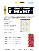
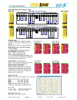
DNSL-DS and DNSL-DR: Standstill, motion and direction monitoring
DNSL-DS
DNSL-DS for encoder: connection scheme
O1 O2 O3 O4 B11 B12 B13 B14 B21 B22
Power
Info
Info
B23 B24
P1 P2
Encoder 1
Encoder 2
Potential Ausgänge/ Outputs
Eingänge / Inputs
Eingänge / Inputs
A
A*
B
B*
0,8-1Vss SIN/COS
4-5V TTL oder/ or
Encoder signals
Sin
Sin*
Cos
Cos*
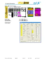
DNSL-DR for resolver: connection scheme
O2
O2
O1 O1
B11 B12 B13 B14 B21 B22
Power
Info
Info
B23 B24
P1 P1
Resolver 1
Resolver 2
Potential Ausgänge/ Outputs
Eingänge / Inputs
Eingänge / Inputs
Resolver
Sin+, Sin-
Cos+, Cos-
Ref+, Ref-
signals
1 -10Vss
DNSL-DS
and
DNSL-DR
are modules to monitor machine motions for standstill, different speeds and the direction
of motion. Each module can monitor two drives. For motion detection the feedback encoder system of the drive is
used.
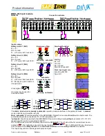
DNSL-DS, DNSL-DR inputs usage
Safety circuit 1
E1
⇒
B11
E2
⇒
B12 and
Q
⇒
B13 control SK1
Safety circuit 2
E1
⇒
B21
E2
⇒
B22 and
Q
⇒
B23 control SK2
E1, E2 may be used in
static or clocked mode.
Clock signal:
E1
E2
All inputs may be used
for optional functions.
Emergency Off
E1
E2
E1
E2
Q
Quit
manually automatic
Protection cover
function
E1
E2
11
12
21
22
E1
E2
Q
11
12
21
22
13
14
23
24
automatic
Permission
function
Q
E2
E1
Quit
E2
E1
manually automatic
Two-hand function
Q1 E1
Q2
E2
only by
E1
⇒
B11
Q1
⇒
B12
E2
⇒
B13
Q2
⇒
B14
controls ZH1
Static input signal
only
according EN 574:
Type IIIC
Wiring Layer
DNCO function
See page 19 or click
here
DNSL-DS
manually
Q
E1
E2
SK1/ 2
automatic
E1
E2
SK1/ 2
Protection Cover function
Q
E1
E2
SK1/ 2
Two-hand function
Q2
E1
E2
ZH1
Q1
>500ms
Q2
OK
<500ms
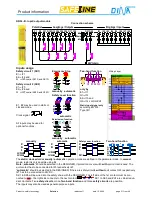
The
static
/
clocked
and
manually
/
automatic
operation mode of SK1 and SK2 are defined in the parameter
mask. In
manual
mode, restart is only possible using
Q
.
Note
: „
automatic
“ should be selected in the DESIGNER, if protection cover switch
with
quit contact is used. The
quit contact has to be connected to B13 respectively B23.
“
automatic
“ should be selected in the DESIGNER, if there are safety circuits
without
quit contact. B13 respectively
B23 has to be connected to 24V DC.
SK1S, SK2S will be wired into the safety chain with the DESIGNER. The left side of the 1st contact must be con-
nected to
, the right side connects to the next contact.
SK1
SK2
+24V
. Two
safety circuits
or
one
safety
circuits
and
one
Two-hand function
are possible. The inputs may also be used as general-purpose inputs.
Summary of Contents for SafeLine DNSL-ZM
Page 1: ...SafeLine Product information Safety for men and machines...
Page 48: ......

