Product information
Products: safety technology
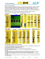
SafeLine
redaction 11 date 10.04.09 page 14 from 48
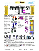
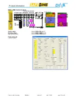
DNSL-ZMB, DNSL-ZMT: Standstill and motion monitoring
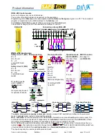
The Central module DNSL-ZMB may be used to monitor two motions for safe standstill and safe speed. For speed
sensing at a motion two proximity switches could be used. This Function is also with DNSL-ZMR available.
Inputs
Operation mode
Virtual
Inputs
Examples
Wiring layer
Monitoring 1
Sensor (S1)
⇒
I11
Sensor (S2)
⇒
I12
Monitoring 2
Sensor (S3)
⇒
I13
Sensor (S4)
⇒
I14
Tool setting mode BA2
Semi automatic mode BA3
Automatic mode BA1
Not-monitored BA1
Tool setting mode BA2
Semi automatic mode BA3
Automatic mode BA1
Not monitored BA1
F11
⇒
F12
⇒
F13
⇒
MT1
⇒
F21
⇒
F22
⇒
F23
⇒
MT1
⇒
Tip contact
Permission contact
Protection cover contact
Protection cover contact
Tip contact
Permission contact
Protection cover contact
Protection cover contact
S1
S2
S3
S4
Zahnrad
Gear
Zahnrad
Gear
Monitoring 1
Monitoring 2
SS1
virtual contact for standstill: closed if standstill, open if
ν
ν
ν
ν
act >
ν
ν
ν
ν
standstill
DZ1
virtual contact for
ν
ν
ν
ν
max: closed if
ν
ν
ν
ν
act <
ν
ν
ν
ν
max , open if
ν
ν
ν
ν
act >
ν
max
SS2
virtual contact for standstill: closed if standstill, open if
ν
ν
ν
ν
act >
ν
ν
ν
ν
standstill
DZ2
virtual contact for
ν
ν
ν
ν
max: closed if
ν
ν
ν
ν
act <
ν
ν
ν
ν
max , open if
ν
ν
ν
ν
act >
ν
max
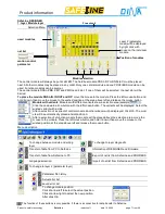
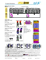
To use motion monitoring the function
DS1
and/or
DS2
in the SafeLine DESIGNER must be selected.
I11, I12
and
I13
are not available for safety circuits in this case.
Selection of the individual speeds is accomplished by entering the corresponding frequency in Hz into the parame-
ter fields.
The maximum Input-frequency for I11 – I14 is 1200Hz.
Proximity switches requirements
:
2 signals with 180° phase offset. One switch at the cog the an other at the gap. Positive switched to 24V DC (PNP)
DNSL-ZMB, DNSL-ZMT: Output usage
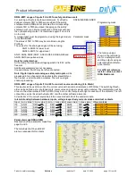
Output O1
function may be defined in the parameter layer to one of the following:
SLOK
: Output indicating
system ready
T8
:
Semi conductor switch
FrqIn
: Frequency input (maximal 1200Hz) single channel motion control.
The output O1 can be redefined as frequency input in the parameter layer to function
as a one-channel not safe motion control. As impulse device a proximity switch may
be used.
Setting the value for the motion control will be done using the PROFIBUS.
The proceeding of programming is received by DINA Elektronik.
SS2
virtual contact is closed at standstill and opened at
ν
ν
ν
ν
act >
ν
ν
ν
ν
standstill
DZ2
virtual contact is closed at
ν
ν
ν
ν
act <
ν
ν
ν
ν
max and opened at
ν
ν
ν
ν
act >
ν
max
To reset the contact DZ2 the maximum of the speed has to be decreased more than
10% a the virtual input RTDS has to be switched to virtual 24V.
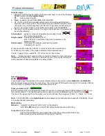
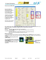
Programming Layer
O2 and O3
are redundant outputs made of two positive switching semiconductors. These outputs may be activated
directly by external inputs or by virtual connections from NC, NO, logic elements, time relays etc.
R13/R14, R23/R24
are 2 relay outputs and they are configurable to the following:
a)
two independent NO contacts, safety category 2, activated by K1, K2
b)
two redundant NO contacts, safety category 4, activated by S1 and Q.
Q may be connected to
or connected via an external input. S1 and Q are displayed in the programming layer
only in this mode.
Version a and b will be factory-made. The factory-made configuration has to be selected via the parameter mask.
Note:
All outputs will be monitored constantly for wrong behavior independent of the function. If an error is de-
tected on one of the outputs, all outputs will be switched off.
Special function:
RTDS:
Virtual input to reset the interlock of the virtual contacts of the motion control at the central mod-
ule and DNSL-DS, DR after the actual values are below the limit values. This virtual input can be also used to reset
safety shutdown mat. The virtual input RTDS must be held at virtual 24V for more then 500ms. For this function a
hardware input I1-I6, I11, I12 rather a hardware input at a function module or virtual output can be used.
Pulse generator via IF1:
With the selection „ON” via the parameter mask the function of a pulse generator (Takt Generator) is possible via
the virtual contact IF1. The right connection can be used to control an hardware output, the left to virtual
The time of the signal „High“ and the signal „Low“ can be defined. The stepping is 100ms. 1 = 100ms, 10 = 1s etc.
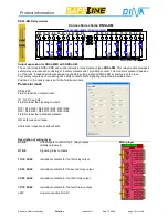
Summary of Contents for SafeLine DNSL-ZM
Page 1: ...SafeLine Product information Safety for men and machines...
Page 48: ......


