Product information
Products: safety technology
SafeLine
redaction 11 date 10.04.09 page 37 from 48
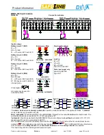
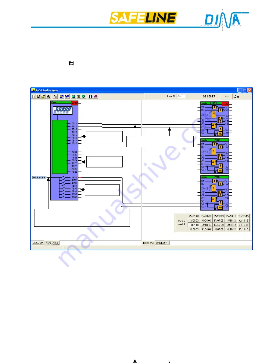
Field bus: Output data
Eight bytes are defined as output-data. Only 3 of the 8 bytes are visible in the DESIGNER (AB1 to AB3). All other
bytes are used for special purposes. The individual data bits will be assigned in the wiring layer of the DESIGNER.
Field bus: Virtual wiring of output data from field bus Master
•
Left click on the
symbol will activate the wiring layer.
•
The
field bus
must be displayed on the left side. The function module at the right side.
•
Clicking on both ends of the virtual connections, will establish the virtual wiring.
•
Example: Field BUS virtual wiring of output data from field bus Master
Field BUS communication
Only cyclic operation is possible between a master category 1 and the slave.
A field BUS communication loss will not disturb the safety function of SafeLine.
Only the output buffer will be cleared. An internal communication loss between the central module and field BUS
slave will be indicated to the master as a static diagnostic.
Configuration
For project planning of the field BUS masters the GSD-DATEI (DINA0AA9.GSD) is provided.
The configuration of the field BUS is carried out using the indication-data-byte B7 (8 bytes input-/output data con-
sistent)
Baud-Rate
Baud-Rates from 9,6K Baud to 12M Baud are supported. Automatic baud rate recognition is provided.
Independent of the field bus Baud-Rate the output-data will be read and the input-data updated every 100ms
respectively 25ms.
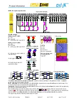
AB11 and AB12 AND connected
The left input for byte 3 may be activated by an
virtual NC-, NO contact, an OR or an AND logic
module or an external input.
Output byte 1
bit 11-18
Output byte 2
bit 21-28
Output byte 3
bit 31-38
Summary of Contents for SafeLine DNSL-ZM
Page 1: ...SafeLine Product information Safety for men and machines...
Page 48: ......


