Product information
Products: safety technology
SafeLine
redaction 11 date 10.04.09 page 10 from 48
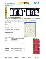
DNSL-ZM: Central module
Every unit contains only one central module.
The number of function modules is dependent on the application.
Programming of the
SafeLine
unit is accomplished with the
SafeLine Designer
program on a PC. The completed
program is transferred via the COM interface to the
Safeline
unit.
The
SafeLine
DESIGNER is special software developed by DINA Elektronik.
The operation voltage (24V DC) is supplied to the clamps A1 und A2.
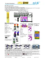
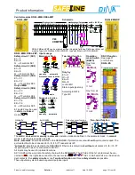
DNSL-ZM
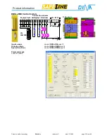
Connection scheme DNSL-ZM
O5
V24
COM PORT
Netzteil
Power supply
UB = 24V DC
I1
I2
I3
I4
I5
I6
O1
O2
O3
O4
O6
O7
A2
A1
0V
24V intern
6A
Eingänge / Inputs
Ausgänge / Outputs
24V DC
DNSL-ZM input usage
Safety circuit 1 (SK1)
E1
⇒
I1
E2
⇒
I2 and
Q
⇒
I3
control SK1S and
SK1Ö
Safety circuit 2 (SK2)
E1
⇒
I4
E2
⇒
I5 and
Q
⇒
I6
control SK2S und
SK2Ö
E1 and E2 may be
used in
static
or
clocked
mode.
E1
E2
All inputs may be used
for optional functions.
Emergency Stop
E1
E2
E1
E2
Q
Quit
manually
automatic
Protection cover function
E1
E2
11
12
21
22
E1
E2
Q
11
12
21
22
13
14
23
24
automatic
Permission function
Q
E2
E1
Quit
E2
E1
manually automatic
Two-hand function
Q1 E1
Q2
E2
only by
E1
⇒
I1
Q1
⇒
I2
E2
⇒
I3
Q2
⇒
I4
control ZH1
Static input signal only
According EN 574:
Type IIIC
Operation mode
Switch (BAWS)
One from three
24V
DC
BA/ Mode
1
2
3
I1 to I3
One from six
24V
DC
BA / Mode
2
3
4
5
6
1
I1 to I6
DNCO Function
See page 12
and
DNSL-DS
Wiring Layer
manually
automatic
Protection cover function
Two-hand function
E1
E2
Q
SK1S, 2S
E1
E2
SK1S, 2S
Q
E1
E2
SK1S, S2
Q2
E1
E2
ZH1
Q1
>500ms
Q2
OK
<500ms
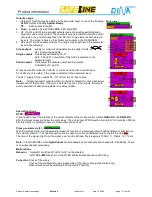
The
static
/
clocked
and
manually
/
automatic
operation mode of SK1 and SK2 are defined in the parameter
mask. In
manual
mode, restart is only possible using
Q
.
Note
: „
automatic
“ should be selected in the DESIGNER, if protection cover switch
with
quit contact is used. The
quit contact has to be connected to I3 respectively I6. “
automatic
“ should be selected in the DESIGNER, if there
are safety circuits
without
quit contact. I3 respectively I6 has to be connected to 24V DC.
SK1S, SK2S will be wired into the safety chain with the DESIGNER. The left side of the 1st contact must be con-
nected to
, the right side connects to the next contact.
SK1
SK2
+24V
. SK1S, SK1Ö, SK2S, SK2Ö and ZH1 are
virtual redundant Contacts. Two
safety circuits
or
one
Two-hand-function
are possible.
The inputs may also be used as general-purpose inputs.
Summary of Contents for SafeLine DNSL-ZM
Page 1: ...SafeLine Product information Safety for men and machines...
Page 48: ......


