1.
Follow the procedures in
Before You Begin
.
2.
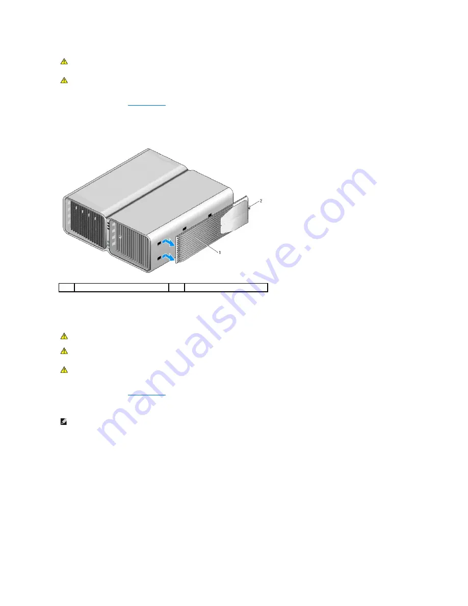
Loosen the captive screw securing the stand to the base of the computer.
3.
Gently slide the stand back, towards the rear of the computer, then pull the stand away from the computer to remove it.
Attaching the Computer Stand
1.
Follow the procedures in
Before You Begin
.
2.
Remove the thumb screw that is installed on the base of the computer.
3.
Insert the six alignment tabs into the corresponding slots on the base of the computer, then slide the stand forward until all six tabs catch in the slots.
4.
Ensure that the screw hole on the stand is aligned with the screw hole on the base of the computer.
5.
Insert the captive screw into the screwhole, then tighten the screw to secure the stand to the base of the computer.
CAUTION:
Your computer is heavy and can be difficult to maneuver. Seek assistance before attempting to lift, move, or tilt the computer and
always lift correctly to avoid injury; avoid bending over while lifting.
CAUTION:
The computer stand should be installed at all times to ensure maximum system stability. Failure to install the stand could result in the
computer tipping over, potentially resulting in bodily injury or damage to the computer.
1
computer stand
2
captive screw
CAUTION:
Before you begin any of the procedures in this section, follow the safety instructions in the
Product Information Guide
.
CAUTION:
Your computer is heavy and can be difficult to maneuver. Seek assistance before attempting to lift, move, or tilt the computer and
always lift correctly to avoid injury; avoid bending over while lifting.
CAUTION:
The computer stand should be installed at all times to ensure maximum system stability. Failure to install the stand could result in the
computer tipping over, potentially resulting in bodily injury or damage to the computer.
NOTE:
If the thumb screw is not already installed in the stand, it has been packaged separately.
Summary of Contents for XPS M2010
Page 20: ...Back to Contents Page ...
Page 25: ...Back to Contents Page ...
Page 39: ......
Page 47: ...2 Tighten the captive screw Back to Contents Page ...
Page 57: ......


