17.
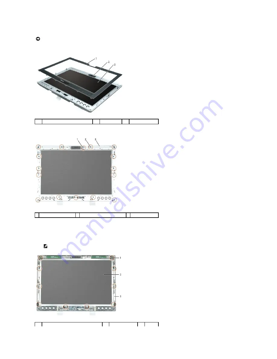
Starting at the top of the panel, remove the black display bezel from around the LCD panel by carefully prying it loose.
18.
On the silver display inlay, remove four M2.5 x 5-mm screws from the holes labeled "A" and twelve M2.5-mm shoulder screws from the remaining holes.
19.
Starting at the top of the panel, remove the silver inlay from around the LCD panel by carefully prying it loose.
20.
On the rails that hold the LCD panel to the display, remove four M2 x 3-mm screws from the left rail, four M2 x 3-mm screws from the right rail, and two
M2 x 3-mm screws from the bottom rail.
NOTICE:
When working on the display, be careful not to touch the camera. The glass on the camera is fragile.
1
black display bezel
2
camera
3
LCD panel
1 M2.5 x 5-mm screws (4)
2 M2.5-mm shoulder screws (12)
3 silver display inlay
NOTE:
Do not remove the screws that hold the display latches in place.
1
M2 x 3-mm screws (10)
2
LCD panel
3
rails
Summary of Contents for XPS M2010
Page 20: ...Back to Contents Page ...
Page 25: ...Back to Contents Page ...
Page 39: ......
Page 47: ...2 Tighten the captive screw Back to Contents Page ...
Page 57: ......


