


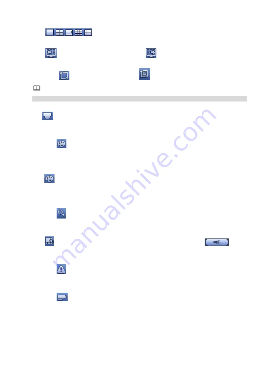
182
Click
to
select corresponding window-split mode and output channels.
4.3.2.4 Previous screen/next screen
Click
to go back to the previous screen, click
to go to the next screen.
4.3.2.5 Tour
Click button
to enable tour, the icon becomes
, you can see the tour is in process.
Note
Close the tour or the triggered tour operation has cancelled, device restore the previous preview video.
4.3.2.6 PTZ
Click
, system goes to the PTZ control interface. Please refer to chapter 4.4.2 PTZ for detailed
information.
4.3.2.7 Color
Click button
, system goes to the color interface. Please refer to chapter 4.3.6.1 Color for detailed
information.
Please make sure system is in one-channel mode.
4.3.2.8 Image
Click
to go to the image interface. Please refer to chapter 4.2.4 Image for detailed information.
Please make sure system is in one-channel mode.
4.3.2.9 Search
Click button
, system goes to search interface. Please refer to chapter 4.6.2 Search for detailed
information.
4.3.2.10 Broadcast
Click
to go to broadcast interface. Select a group name and then click
to begin
broadcast. Please refer to chapter 4.10.5 Broadcast for detailed information.
4.3.2.11 Alarm Status
Click button
, system goes to alarm status interface. It is to view device status and channel status.
Please refer to chapter 4.10.2.3.1 Alarm status for detailed information.
4.3.2.12 Channel Info
Click button
, system goes to the channel information setup interface. It is to view information of the
corresponding channel. See Figure 4-62.
Summary of Contents for DHI-NVR5224-24P-4KS2
Page 1: ...Network Video Recorder User s Manual V4 3 2...
Page 136: ...124 Figure 3 5 3 6 6 NVR42N Series Please refer to Figure 3 6 for connection sample Figure 3 6...
Page 140: ...128 Figure 3 11 3 6 12 NVR42V 8P Series Please refer to Figure 3 12 for connection sample...
Page 141: ...129 Figure 3 12...
Page 155: ...143 Figure 4 15 Step 2 Click device display edit interface See Figure 4 16...
Page 218: ...206 Figure 4 93 Figure 4 94...
Page 238: ...226 Figure 4 110 Figure 4 111 Figure 4 112...
Page 249: ...237 Figure 4 123 Figure 4 124...
Page 251: ...239 Figure 4 126 Click draw button to draw the zone See Figure 4 127...
Page 255: ...243 Figure 4 130 Click Draw button to draw a zone See Figure 4 131 Figure 4 131...
Page 260: ...248 Figure 4 136 Click draw button to draw the zone See Figure 4 137...
Page 273: ...261 Figure 4 148 Figure 4 149...
Page 274: ...262 Figure 4 150 Figure 4 151...
Page 384: ...372 Figure 5 60 Figure 5 61...
Page 385: ...373 Figure 5 62 Figure 5 63...
Page 409: ...397 Figure 5 96 Figure 5 97...