


190
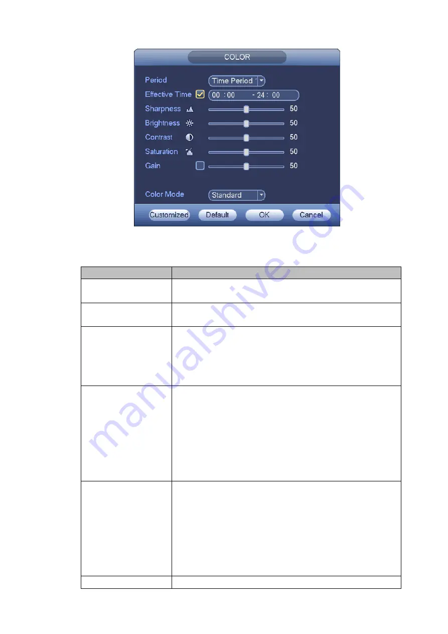
Figure 4-71
Please refer to the following sheet for detailed information.
Item
Note
Period
There are two periods in one day. You can set different
sharpness, brightness, and contrast setup for different periods.
Effective Time
Check the box here to enable this function and then set period
time.
Sharpness
The value here is to adjust the edge of the video. The value
ranges from 0 to 100. The larger the value is, the clear the edge
is and vice versa. Please note there is noise if the value here is
too high. The default value is 50 and the recommended value
ranges from 40 to 60.
Brightness
It is to adjust monitor window bright. The value ranges from 0 to
100. The default value is 50.
The larger the number, the bright the video is. When you input
the value here, the bright section and the dark section of the
video will be adjusted accordingly. You can use this function
when the whole video is too dark or too bright. Please note the
video may become hazy if the value is too high. The
recommended value ranges from 40 to 60.
Contrast
It is to adjust monitor window contrast. The value ranges from 0
to 100. The default value is 50.
The larger the number, the higher the contrast is. You can use
this function when the whole video bright is OK but the contrast
is not proper. Please note the video may become hazy if the
value is too low. If this value is too high, the dark section may
lack brightness while the bright section may over exposure .The
recommended value ranges from 40 to 60.
Saturation
It is to adjust monitor window saturation. The value ranges from
Summary of Contents for DHI-NVR5224-24P-4KS2
Page 1: ...Network Video Recorder User s Manual V4 3 2...
Page 136: ...124 Figure 3 5 3 6 6 NVR42N Series Please refer to Figure 3 6 for connection sample Figure 3 6...
Page 140: ...128 Figure 3 11 3 6 12 NVR42V 8P Series Please refer to Figure 3 12 for connection sample...
Page 141: ...129 Figure 3 12...
Page 155: ...143 Figure 4 15 Step 2 Click device display edit interface See Figure 4 16...
Page 218: ...206 Figure 4 93 Figure 4 94...
Page 238: ...226 Figure 4 110 Figure 4 111 Figure 4 112...
Page 249: ...237 Figure 4 123 Figure 4 124...
Page 251: ...239 Figure 4 126 Click draw button to draw the zone See Figure 4 127...
Page 255: ...243 Figure 4 130 Click Draw button to draw a zone See Figure 4 131 Figure 4 131...
Page 260: ...248 Figure 4 136 Click draw button to draw the zone See Figure 4 137...
Page 273: ...261 Figure 4 148 Figure 4 149...
Page 274: ...262 Figure 4 150 Figure 4 151...
Page 384: ...372 Figure 5 60 Figure 5 61...
Page 385: ...373 Figure 5 62 Figure 5 63...
Page 409: ...397 Figure 5 96 Figure 5 97...