


108
(
).
Connect the NC port of the alarm device to the alarm input port (ALARM) of the NVR.
When there is peripheral power supplying for the alarm device, please make sure it is earthed with
the NVR.
2.3.3
Alarm input and output port
There is peripheral power supplying for the external alarm device.
In case overload may result in NVR damage, please refer to the following relay specifications for
detailed information.
A/B cable of the RS485 is for the A/B cable connection of the speed PTZ.
2.3.4
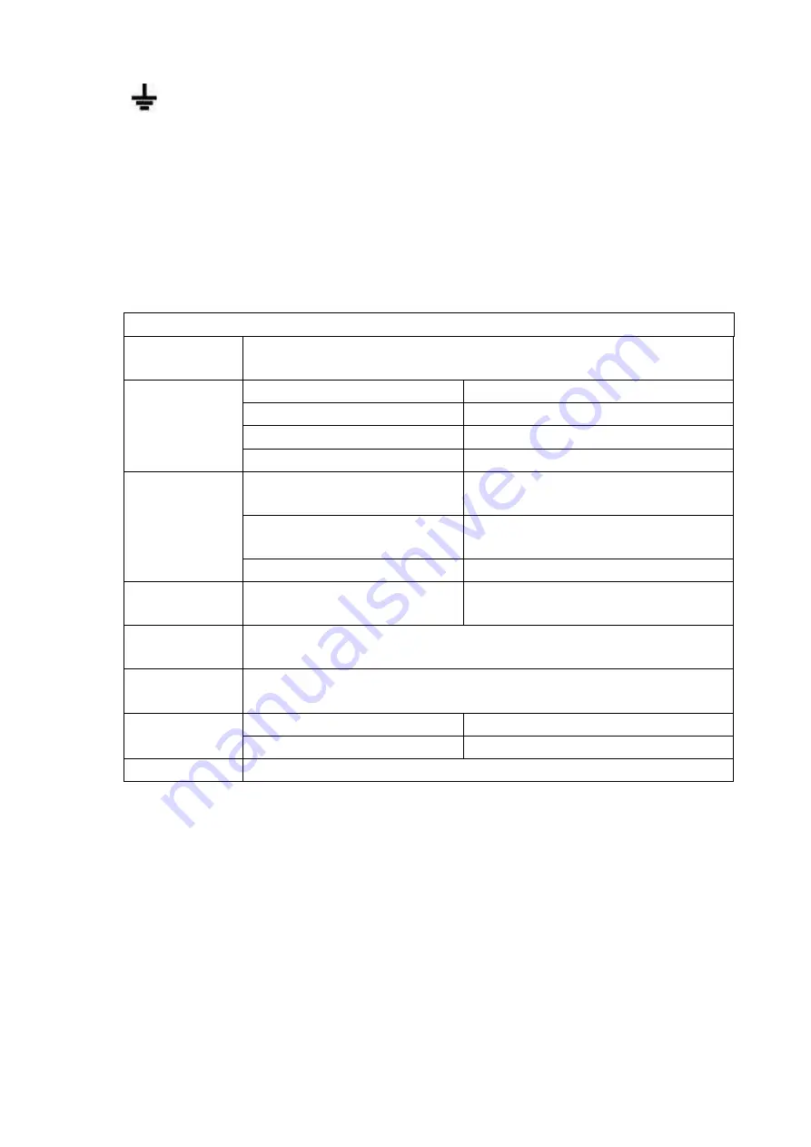
Alarm relay specifications
Model:
JRC-27F
Material of the
touch
Silver
Rating
(
Resistance
Load
)
Rated switch capacity
30VDC 2A, 125VAC 1A
Maximum switch power
125VA 160W
Maximum switch voltage
250VAC, 220VDC
Maximum switch currency
1A
Insulation
Between touches with same
polarity
1000VAC 1minute
Between touches with different
polarity
1000VAC 1minute
Between touch and winding
1000VAC 1minute
Surge voltage
Between touches with same
polarity
1500V (10×160us)
Length of open
time
3ms max
Length of close
time
3ms max
Longevity
Mechanical
50×106
MIN
(3Hz)
Electrical
200×103
MIN
(0.5Hz)
Temperature
-40
℃
~+70
℃
2.4 Bidirectional talk
2.4.1
Device-end to PC-end
Device Connection
Please connect the speaker or the pickup to the first audio input port in the device rear panel. Then
connect the earphone or the sound box to the audio output port in the PC.
Login the Web and then enable the corresponding channel real-time monitor.
Please refer to the following interface to enable bidirectional talk. See Figure 2-67.
Summary of Contents for DHI-NVR5224-24P-4KS2
Page 1: ...Network Video Recorder User s Manual V4 3 2...
Page 136: ...124 Figure 3 5 3 6 6 NVR42N Series Please refer to Figure 3 6 for connection sample Figure 3 6...
Page 140: ...128 Figure 3 11 3 6 12 NVR42V 8P Series Please refer to Figure 3 12 for connection sample...
Page 141: ...129 Figure 3 12...
Page 155: ...143 Figure 4 15 Step 2 Click device display edit interface See Figure 4 16...
Page 218: ...206 Figure 4 93 Figure 4 94...
Page 238: ...226 Figure 4 110 Figure 4 111 Figure 4 112...
Page 249: ...237 Figure 4 123 Figure 4 124...
Page 251: ...239 Figure 4 126 Click draw button to draw the zone See Figure 4 127...
Page 255: ...243 Figure 4 130 Click Draw button to draw a zone See Figure 4 131 Figure 4 131...
Page 260: ...248 Figure 4 136 Click draw button to draw the zone See Figure 4 137...
Page 273: ...261 Figure 4 148 Figure 4 149...
Page 274: ...262 Figure 4 150 Figure 4 151...
Page 384: ...372 Figure 5 60 Figure 5 61...
Page 385: ...373 Figure 5 62 Figure 5 63...
Page 409: ...397 Figure 5 96 Figure 5 97...