


351
Video/audio
You can enable or disable the video/audio. The main stream is
enabled by default. After enable the audio function, the record file
is composite file consisting of the video and audio. For the sub
stream 1, please enable video first and then enable audio
function.
Audio format
Set audio encode format.
Note
Different series products support different audio encode mode.
Please refer to the actual interface for detailed information.
Sampling rate
Audio sampling rate refers to the sampling amount within 1
second. The higher the value is, the better the audio is. The
default setup is 8K.
Watermark
enable
This function allows you to verify the video is tampered or not.
Here you can select watermark bit stream, watermark mode and
watermark character. Default character is DigitalCCTV. The max
length is 85-digit. The character can only include number,
character and underline.
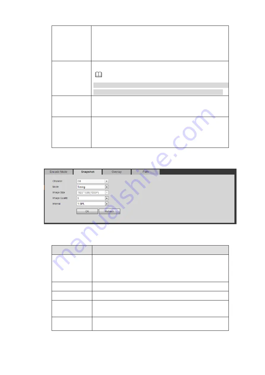
5.10.1.3.2 Snapshot
The snapshot interface is shown as in Figure 5-28.
Figure 5-28
Please refer to the following sheet for detailed information.
Parameter
Function
Snapshot type
There are two modes: Regular (schedule) and Trigger.
Regular snapshot is valid during the specified period you
set.
Trigger snapshot only is valid when motion detect alarm,
tampering alarm or local activation alarm occurs.
Image size
It is the same with the resolution of the main stream.
Quality
It is to set the image quality. There are six levels.
Interval
It is to set snapshot frequency. The value ranges from 1s to 7s.
Or you can set customized value. The max setup is
3600s/picture.
Copy
Click it; you can copy current channel setup to other channel(s).
5.10.1.3.3 Video Overlay
The video overlay interface is shown as in Figure 5-29.
Summary of Contents for DHI-NVR5224-24P-4KS2
Page 1: ...Network Video Recorder User s Manual V4 3 2...
Page 136: ...124 Figure 3 5 3 6 6 NVR42N Series Please refer to Figure 3 6 for connection sample Figure 3 6...
Page 140: ...128 Figure 3 11 3 6 12 NVR42V 8P Series Please refer to Figure 3 12 for connection sample...
Page 141: ...129 Figure 3 12...
Page 155: ...143 Figure 4 15 Step 2 Click device display edit interface See Figure 4 16...
Page 218: ...206 Figure 4 93 Figure 4 94...
Page 238: ...226 Figure 4 110 Figure 4 111 Figure 4 112...
Page 249: ...237 Figure 4 123 Figure 4 124...
Page 251: ...239 Figure 4 126 Click draw button to draw the zone See Figure 4 127...
Page 255: ...243 Figure 4 130 Click Draw button to draw a zone See Figure 4 131 Figure 4 131...
Page 260: ...248 Figure 4 136 Click draw button to draw the zone See Figure 4 137...
Page 273: ...261 Figure 4 148 Figure 4 149...
Page 274: ...262 Figure 4 150 Figure 4 151...
Page 384: ...372 Figure 5 60 Figure 5 61...
Page 385: ...373 Figure 5 62 Figure 5 63...
Page 409: ...397 Figure 5 96 Figure 5 97...