


378
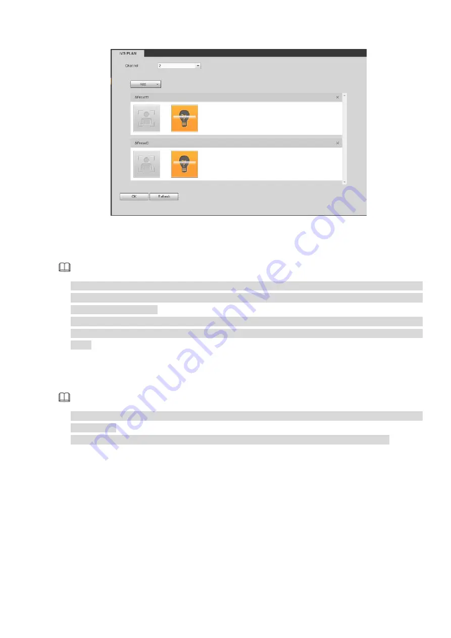
Figure 5-69
Click OK button to complete the setup.
Note
The NVR supports general behavior analytics (IVS), human face detection, heat map, and people
counting. Different network camera supports different smart plans. Please refer to the actual product
for detailed information.
The general behavior analytics (IVS) and human face detection function cannot be valid at the same
time. For example, when add the IVS plan to the preset 1, the human face detection icon becomes
grey.
5.10.3.2 IVS (Behavior Analytics) (Optional)
Once the object state has reached the threshold, NVR can trigger an intelligent alarm.
Note
This function is for some series product only. Please refer to the actual product for detailed
information.
The IVS function and the human face detection function cannot be valid at the same time.
The IVS function environment shall meet the following requirements:
The object total size shall not be more than 10% of the whole video.
The object size on the video shall not be more than 10pixels*10 pixels. The abandoned object size
shall be more than 15pixels*15 pixels (CIF resolution). The object width shall not be more than 1/3 of
the video height and width. The recommended height is 10% of the video.
The object and the background brightness different shall be more than 10 grey levels.
The object shall remain on the video for more than 2 seconds. The moving distance is larger than its
own width and shall not be smaller than 15pixels (CIF resolution).
The surveillance environment shall not be too complicated. The IVS function is not suitable for the
environment of too many objects or the changing light.
The surveillance environment shall not contain glasses, reflection light from the ground, and water.
Free of tree branches, shadow, mosquito and bugs. Do not use the IVS function in the backlight
Summary of Contents for DHI-NVR5224-24P-4KS2
Page 1: ...Network Video Recorder User s Manual V4 3 2...
Page 136: ...124 Figure 3 5 3 6 6 NVR42N Series Please refer to Figure 3 6 for connection sample Figure 3 6...
Page 140: ...128 Figure 3 11 3 6 12 NVR42V 8P Series Please refer to Figure 3 12 for connection sample...
Page 141: ...129 Figure 3 12...
Page 155: ...143 Figure 4 15 Step 2 Click device display edit interface See Figure 4 16...
Page 218: ...206 Figure 4 93 Figure 4 94...
Page 238: ...226 Figure 4 110 Figure 4 111 Figure 4 112...
Page 249: ...237 Figure 4 123 Figure 4 124...
Page 251: ...239 Figure 4 126 Click draw button to draw the zone See Figure 4 127...
Page 255: ...243 Figure 4 130 Click Draw button to draw a zone See Figure 4 131 Figure 4 131...
Page 260: ...248 Figure 4 136 Click draw button to draw the zone See Figure 4 137...
Page 273: ...261 Figure 4 148 Figure 4 149...
Page 274: ...262 Figure 4 150 Figure 4 151...
Page 384: ...372 Figure 5 60 Figure 5 61...
Page 385: ...373 Figure 5 62 Figure 5 63...
Page 409: ...397 Figure 5 96 Figure 5 97...