


192
Display the intelligent rule(s): Check the box to enable IVS function, system can display IVS rule on
the preview interface.
Please note this function is for some series only.
Resolution: There are five options: 1280×1024 (Default), 1280×720, 1920×1080, 1024×768 and
3840×2160. Please note the system needs to reboot to activate current setup.
Please note
3840×2160 is for some series only.
VGA+HDMI2: It is for dual-screen operation. Please select from the dropdown list according to your
actual situation. Click Apply button, system needs to restart to activate new setup. For example,
32+4 means for VGA, system max supports 32-window split and for HDMI2, system max supports
4-window split.
Please note this function is for some series only.
Transparency: Here is for you to adjust menu transparency. The higher the value is, the better
transparent the menu is.
Time display: You can select to display time or not when system is playback.
Channel display: You can select to channel name or not when system is playback.
Image enhance: Check the box; you can optimize the margin of the preview video.
Original scale: Check the box here to select a corresponding channel; it can restore video original
scale.
Click OK button to save current setup.
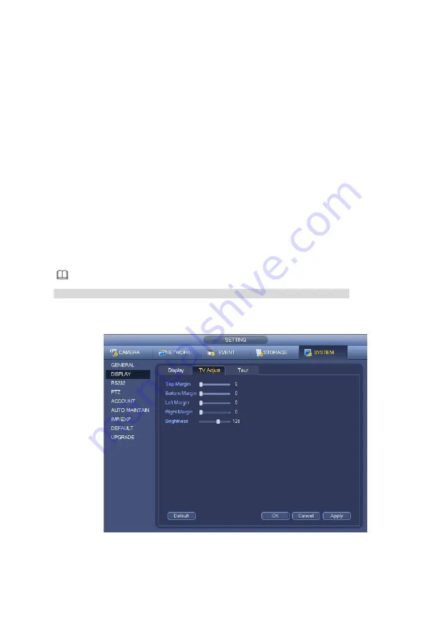
4.3.6.3 TV adjust
Note
Some series product supports TV adjust function. This function is disabled by default.
From Main Menu->Setting->System->Display->TV adjust; you can go to the following interface. See
Figure 4-72. Here you can set margins and brightness.
Figure 4-73
4.3.6.4 Preview Tour Parameters
Summary of Contents for DHI-NVR5224-24P-4KS2
Page 1: ...Network Video Recorder User s Manual V4 3 2...
Page 136: ...124 Figure 3 5 3 6 6 NVR42N Series Please refer to Figure 3 6 for connection sample Figure 3 6...
Page 140: ...128 Figure 3 11 3 6 12 NVR42V 8P Series Please refer to Figure 3 12 for connection sample...
Page 141: ...129 Figure 3 12...
Page 155: ...143 Figure 4 15 Step 2 Click device display edit interface See Figure 4 16...
Page 218: ...206 Figure 4 93 Figure 4 94...
Page 238: ...226 Figure 4 110 Figure 4 111 Figure 4 112...
Page 249: ...237 Figure 4 123 Figure 4 124...
Page 251: ...239 Figure 4 126 Click draw button to draw the zone See Figure 4 127...
Page 255: ...243 Figure 4 130 Click Draw button to draw a zone See Figure 4 131 Figure 4 131...
Page 260: ...248 Figure 4 136 Click draw button to draw the zone See Figure 4 137...
Page 273: ...261 Figure 4 148 Figure 4 149...
Page 274: ...262 Figure 4 150 Figure 4 151...
Page 384: ...372 Figure 5 60 Figure 5 61...
Page 385: ...373 Figure 5 62 Figure 5 63...
Page 409: ...397 Figure 5 96 Figure 5 97...