


156
Record Type: Please check the box to select corresponding record type. There are six
types: Regular/MD (motion detect)/Alarm/MD&Alarm/IVS/POS.
Week day: There are eight options: ranges from Saturday to Sunday and all.
Holiday: It is to set holiday setup. Please note you need to go to the General interface (Main
Menu->Setting->System->General) to add holiday first. Otherwise you cannot see this item.
Pre-record: System can pre-record the video before the event occurs into the file. The value
ranges from 1 to 30 seconds depending on the bit stream.
Redundancy: System supports redundancy backup function. It allows you backup recorded
file in two disks. You can highlight Redundancy button to activate this function. Please note,
before enable this function, please set at least one HDD as redundant. (Main
menu->Setting->Storage->HDD Manager). Please note this function is null if there is only
one HDD.
ANR: It is to save video to the SD card of the network camera in case the network
connection fails. The value ranges from 0s
~
43200s. After the network connection resumed,
the system can get the video from the SD card and there is no risk of record loss.
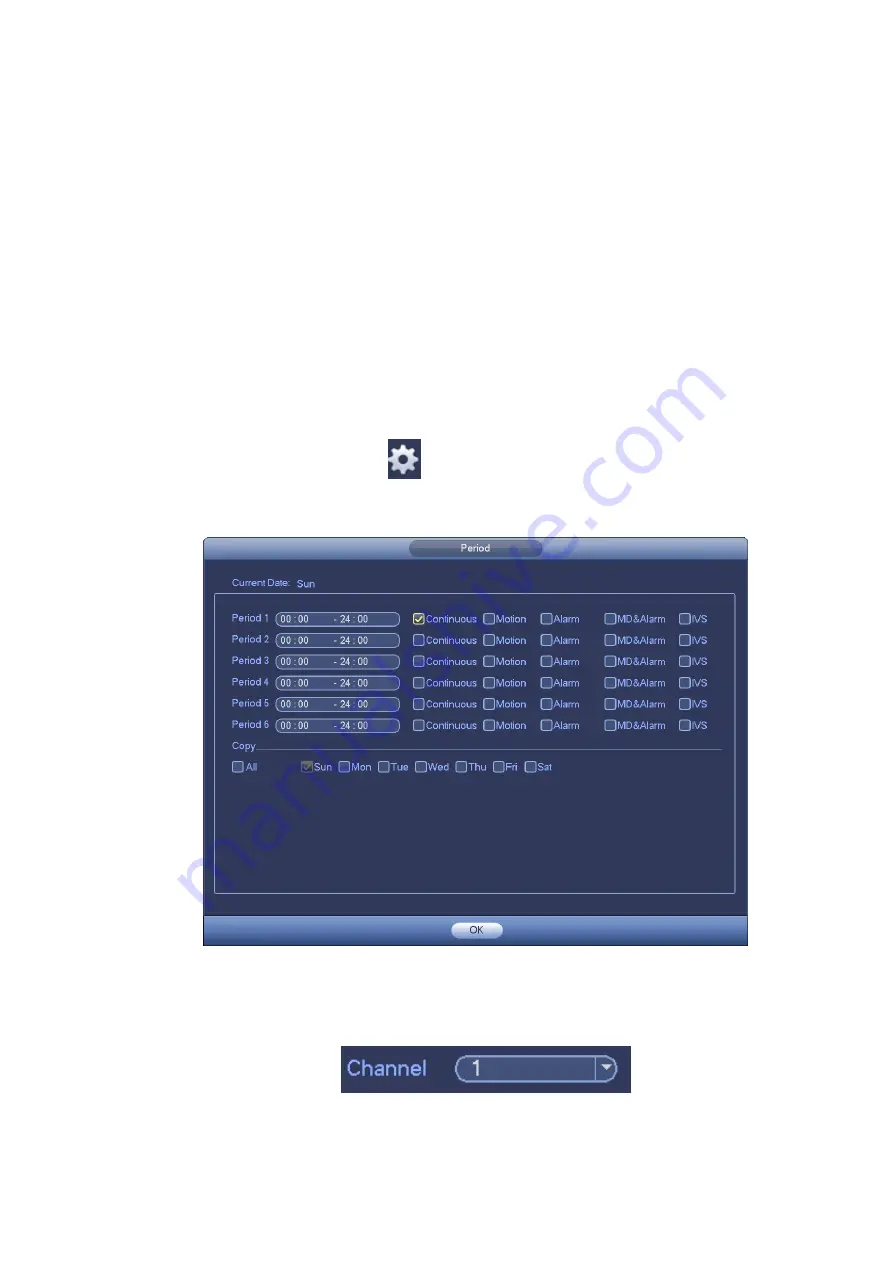
Period setup: Click button
after one date or a holiday, you can see an interface shown
as in Figure 4-28.There are five record types: regular, motion detection (MD), Alarm, MD &
alarm and IVS.
Figure 4-28
Please following the steps listed below to draw the period manually.
Step 1 Select a channel you want to set. See Figure 4-29.
Figure 4-29
Step 2 Set record type. See Figure 4-30.
Summary of Contents for DHI-NVR5224-24P-4KS2
Page 1: ...Network Video Recorder User s Manual V4 3 2...
Page 136: ...124 Figure 3 5 3 6 6 NVR42N Series Please refer to Figure 3 6 for connection sample Figure 3 6...
Page 140: ...128 Figure 3 11 3 6 12 NVR42V 8P Series Please refer to Figure 3 12 for connection sample...
Page 141: ...129 Figure 3 12...
Page 155: ...143 Figure 4 15 Step 2 Click device display edit interface See Figure 4 16...
Page 218: ...206 Figure 4 93 Figure 4 94...
Page 238: ...226 Figure 4 110 Figure 4 111 Figure 4 112...
Page 249: ...237 Figure 4 123 Figure 4 124...
Page 251: ...239 Figure 4 126 Click draw button to draw the zone See Figure 4 127...
Page 255: ...243 Figure 4 130 Click Draw button to draw a zone See Figure 4 131 Figure 4 131...
Page 260: ...248 Figure 4 136 Click draw button to draw the zone See Figure 4 137...
Page 273: ...261 Figure 4 148 Figure 4 149...
Page 274: ...262 Figure 4 150 Figure 4 151...
Page 384: ...372 Figure 5 60 Figure 5 61...
Page 385: ...373 Figure 5 62 Figure 5 63...
Page 409: ...397 Figure 5 96 Figure 5 97...