


289
Refer to the following table for PoE notice.
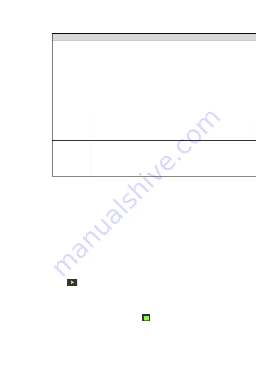
Type
Note
Connect
camera to the
PoE
After connect the camera to the PoE, NVR allocate an IP address in the
specified IP segment to the camera. NVR tries to use
arp ping to set.
If the
NVR has enabled the DHCP function, it uses DHCP to set.
After successfully set IP address, NVR can send out broadcast via the
switch and get the corresponding response. Now The camera has
registered to the NVR. Go to the preview interface, the corresponding
channel has been used and there is a small PoE icon at the top left
corner.
Go to the Register interface to view the connected device list, you can
see the PoE channel number, PoE port information and etc. Click IP
search to display or refresh the information.
Remove
camera
from
the PoE port
After remove the camera network cable from the PoE port, the channel
displa
ys “Cannot
find the network host”. On the registration interface
, the IP
address is shown as offline.
The
mapping
policy
when
connect
a
camera to the
PoE port.
The PoE port and the channel window is one to one correspondence. For
example, connect a network camera to PoE port 1, it register to channel 1 by
default.
4.8.2
Network Test
In this interface, you can see network test and network load information.
4.8.2.1 Network Test
From main menu->Info-Network->Test, the network test interface is shown as in Figure 4-182.
Destination IP: Please input valid IPV4 address and domain name.
Test: Click it to test the connection with the destination IP address. The test results can display
average delay and packet loss rate and you can also view the network status as OK, bad, no
connection and etc.
Network Sniffer backup: Please insert USB2.0 device and click the Refresh button, you can view the
device on the following column. You can use the dropdown list to select peripheral device. Click
Browse button to select the snap path. The steps here are same as preview backup operation.
You can view all connected network adapter names (including Ethernet, PPPoE, WIFI, and 3G), you can
click the button
on the right panel to begin Sniffer. Click the grey stop button to stop. Please note
system cannot Sniffer several network adapters at the same time.
After Sniffer began, you can exit to implement corresponding network operation such as login WEB,
monitor. Please go back to Sniffer interface to click
stop Sniffer. System can save the packets to the
specified path. The file is named after “Network adapter name+time”. You can use software such as
Wireshark to open the packets on the PC for the professional engineer to solve complicated problems.
Summary of Contents for DHI-NVR5224-24P-4KS2
Page 1: ...Network Video Recorder User s Manual V4 3 2...
Page 136: ...124 Figure 3 5 3 6 6 NVR42N Series Please refer to Figure 3 6 for connection sample Figure 3 6...
Page 140: ...128 Figure 3 11 3 6 12 NVR42V 8P Series Please refer to Figure 3 12 for connection sample...
Page 141: ...129 Figure 3 12...
Page 155: ...143 Figure 4 15 Step 2 Click device display edit interface See Figure 4 16...
Page 218: ...206 Figure 4 93 Figure 4 94...
Page 238: ...226 Figure 4 110 Figure 4 111 Figure 4 112...
Page 249: ...237 Figure 4 123 Figure 4 124...
Page 251: ...239 Figure 4 126 Click draw button to draw the zone See Figure 4 127...
Page 255: ...243 Figure 4 130 Click Draw button to draw a zone See Figure 4 131 Figure 4 131...
Page 260: ...248 Figure 4 136 Click draw button to draw the zone See Figure 4 137...
Page 273: ...261 Figure 4 148 Figure 4 149...
Page 274: ...262 Figure 4 150 Figure 4 151...
Page 384: ...372 Figure 5 60 Figure 5 61...
Page 385: ...373 Figure 5 62 Figure 5 63...
Page 409: ...397 Figure 5 96 Figure 5 97...