


227
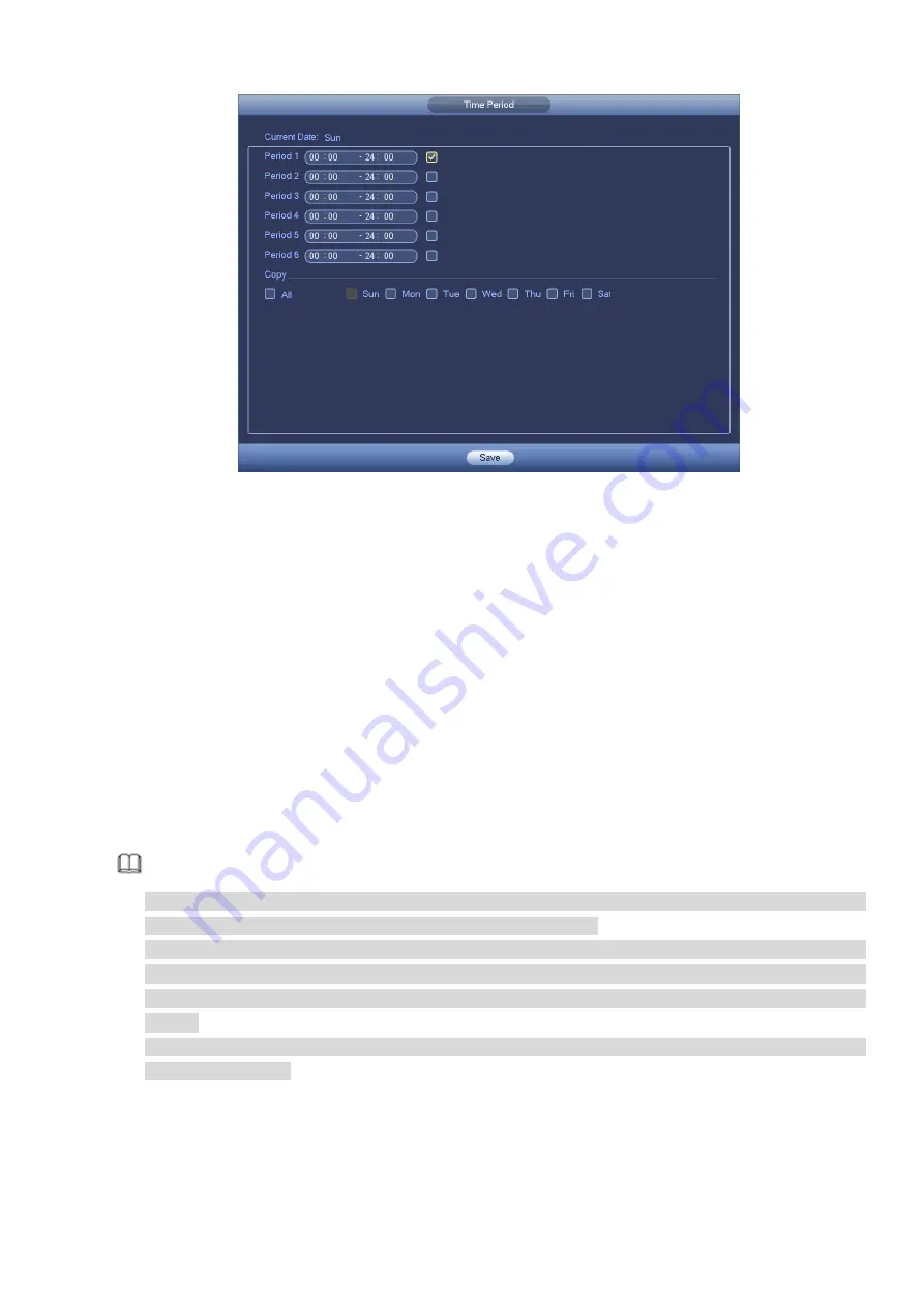
Figure 4-113
Motion detect here only has relationship with the sensitivity and region setup. It has no relationship
with other setups.
4.7.1.2 Tampering
When someone viciously masks the lens, or the output video is in one-color due to the environments
light change, the system can alert you to guarantee video continuity. Tampering interface is shown as
in Figure 4-114
. You can enable “Alarm output “or “Show message” function when tampering alarm
occurs.
Sensitivity: The value ranges from 1 to 6. It mainly concerns the brightness. The level 6 has the
higher sensitivity than level 1. The default setup is 3.
Tips:
You can enable preset/tour/pattern activation operation when video loss occurs.
Please refer to chapter 4.7.1.1 motion detection for detailed information.
Note
In Detect interface, copy/paste function is only valid for the same type, which means you cannot
copy a channel setup in video loss mode to tampering mode.
About Default function. Since detection channel and detection type may not be the same , system
can only restore default setup of current detect type. For example, if you click Default button at
the tampering interface, you can only restore default tampering setup. It is null for other detect
types.
System only enables tampering function during the period you set here. It is null for motion detect
or video loss type.
Summary of Contents for DHI-NVR5224-24P-4KS2
Page 1: ...Network Video Recorder User s Manual V4 3 2...
Page 136: ...124 Figure 3 5 3 6 6 NVR42N Series Please refer to Figure 3 6 for connection sample Figure 3 6...
Page 140: ...128 Figure 3 11 3 6 12 NVR42V 8P Series Please refer to Figure 3 12 for connection sample...
Page 141: ...129 Figure 3 12...
Page 155: ...143 Figure 4 15 Step 2 Click device display edit interface See Figure 4 16...
Page 218: ...206 Figure 4 93 Figure 4 94...
Page 238: ...226 Figure 4 110 Figure 4 111 Figure 4 112...
Page 249: ...237 Figure 4 123 Figure 4 124...
Page 251: ...239 Figure 4 126 Click draw button to draw the zone See Figure 4 127...
Page 255: ...243 Figure 4 130 Click Draw button to draw a zone See Figure 4 131 Figure 4 131...
Page 260: ...248 Figure 4 136 Click draw button to draw the zone See Figure 4 137...
Page 273: ...261 Figure 4 148 Figure 4 149...
Page 274: ...262 Figure 4 150 Figure 4 151...
Page 384: ...372 Figure 5 60 Figure 5 61...
Page 385: ...373 Figure 5 62 Figure 5 63...
Page 409: ...397 Figure 5 96 Figure 5 97...