


294
If there is remote directory, system can create corresponding folder under the FTP root path and
then create different folders according to IP address, time and channel.
File length: File length is upload file length. When setup is larger than the actual file length, system
will upload the whole file. When setup here is smaller than the actual file length, system only uploads
the set length and auto ignore the left section. When interval value is 0, system uploads all
corresponding files.
Image upload interval: It is the image upload interval. If the image upload interval is larger than the
image snapshot frequency, system just uploads the lasted image.
If the image interval is 5 seconds and the snapshot frequency is 2 seconds, system will send out
the latest image at the buffer at 5 seconds.
If the image upload interval is smaller than the snapshot frequency, system will upload at the
snapshot frequency. For example, if the image interval is 5 seconds and the snapshot frequency
is 10 seconds, system will send out the image at 10 seconds.
From main menu->Setting->Camera->Encode->Snapshot to set snapshot frequency.
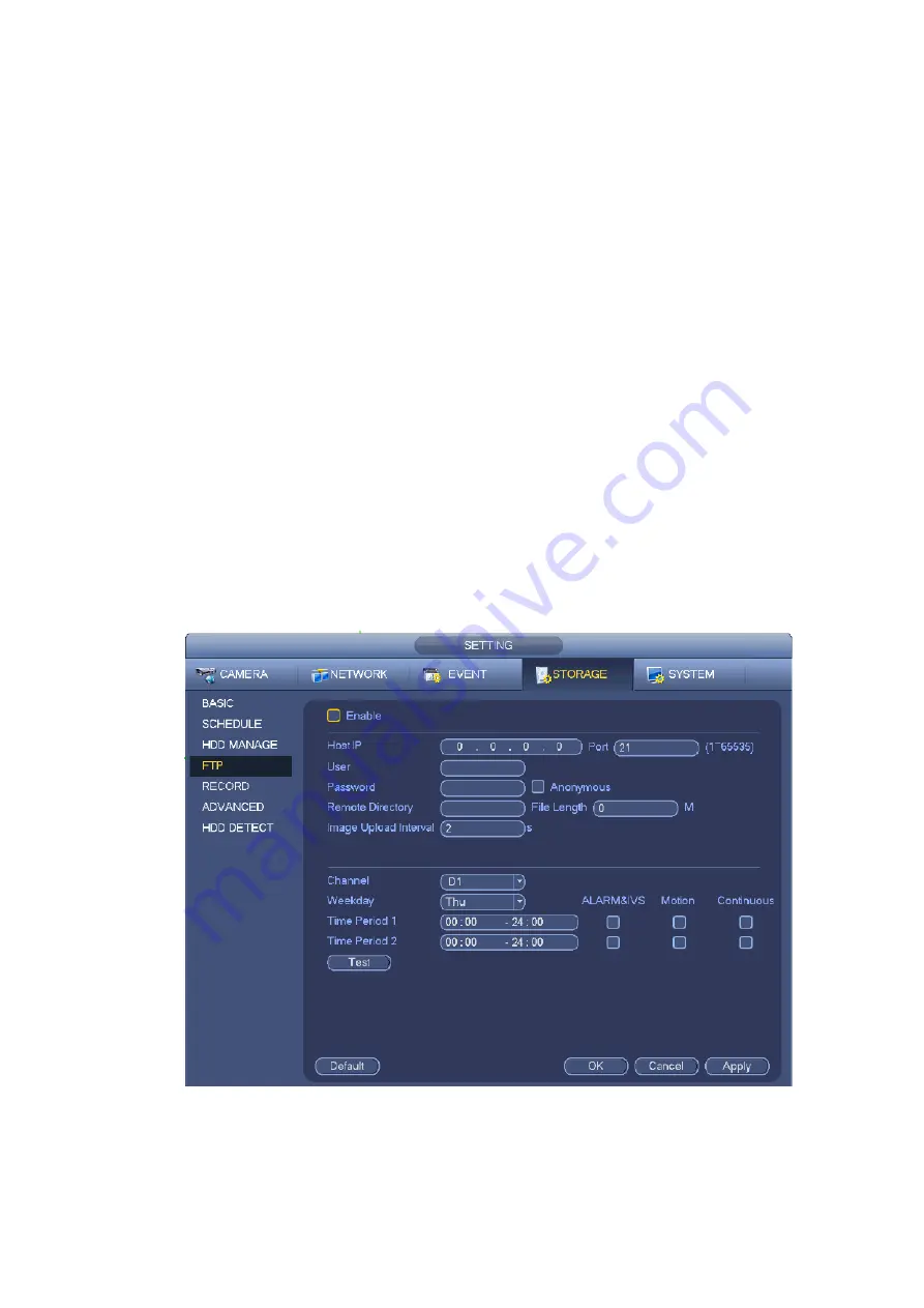
Channel: Select a channel from the dropdown list and then set week, period and record type.
Week day/Period: Please select from the dropdown list and for each day, you can set two periods.
Type: Please select uploaded record type (Alarm/intelligent/motion detect/regular). Please check the
box to select upload type.
Step 3 Click the Test button, you can see the corresponding dialogue box to see the FTP connection
is OK or not.
Step 4 Click Apply or Save to complete setup.
Figure 4-186
4.9.5
Record Control
After you set schedule record or schedule snapshot function, please set auto record/snapshot function so
Summary of Contents for DHI-NVR5224-24P-4KS2
Page 1: ...Network Video Recorder User s Manual V4 3 2...
Page 136: ...124 Figure 3 5 3 6 6 NVR42N Series Please refer to Figure 3 6 for connection sample Figure 3 6...
Page 140: ...128 Figure 3 11 3 6 12 NVR42V 8P Series Please refer to Figure 3 12 for connection sample...
Page 141: ...129 Figure 3 12...
Page 155: ...143 Figure 4 15 Step 2 Click device display edit interface See Figure 4 16...
Page 218: ...206 Figure 4 93 Figure 4 94...
Page 238: ...226 Figure 4 110 Figure 4 111 Figure 4 112...
Page 249: ...237 Figure 4 123 Figure 4 124...
Page 251: ...239 Figure 4 126 Click draw button to draw the zone See Figure 4 127...
Page 255: ...243 Figure 4 130 Click Draw button to draw a zone See Figure 4 131 Figure 4 131...
Page 260: ...248 Figure 4 136 Click draw button to draw the zone See Figure 4 137...
Page 273: ...261 Figure 4 148 Figure 4 149...
Page 274: ...262 Figure 4 150 Figure 4 151...
Page 384: ...372 Figure 5 60 Figure 5 61...
Page 385: ...373 Figure 5 62 Figure 5 63...
Page 409: ...397 Figure 5 96 Figure 5 97...