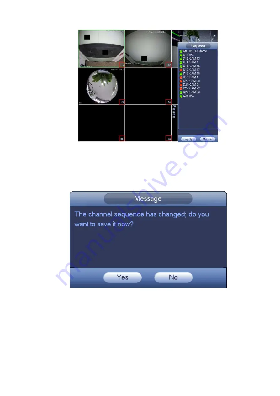
Dahua DHI-NVR5224-24P-4KS2 User Manual Download Page 201

189 


Figure 4-69 

Step 3


Click Apply to save current channel sequence. 


After you change the channel sequence, click Cancel button or right click mouse, device pops 

up the dialogue box. See Figure 4-70. 


Click OK to save current settings.   


Click Cancel to exit without saving the settings.   


Figure 4-70 


4.3.6

  Preview Display Effect Setup   

4.3.6.1 Video Color   

Here  you  can  set  hue,  brightness,  contrast,  saturation,  gain,  white  level,  color  mode  and  etc.  See 

Figure 4-71. 

Summary of Contents for DHI-NVR5224-24P-4KS2

Page 1: ...Network Video Recorder User s Manual V4 3 2...

Page 2: ...HTTP and TCP ports for systems These are the two ports used to communicate and to view video feeds remotely These ports can be changed to any set of numbers between 1025 65535 Avoiding the default po...

Page 3: ...s recommended when the function is not used in real applications 11 SNMP Disable SNMP if you are not using it If you are using SNMP you should do so only temporarily for tracing and testing purposes o...

Page 4: ...1 3 17 NVR48 48 16P Series 31 1 3 18 NVR42V 8P Series 33 1 3 19 NVR41 4KS2 41 P 4KS2 41 8P 4KS2 Series 35 1 3 20 NVR41HS 4KS2 41HS P 4KS2 41HS 8P 4KS2 Series 37 1 3 21 NVR42 4KS2 42 P 4KS2 42 8P 4KS2...

Page 5: ...4KS2 21HS P 4K S2 21HS 8P 4KS2 Series 80 2 2 5 NVR41HS W S2 Series 82 2 2 6 NVR22 S2 22 P S2 22 8P S2 2A16 22 4KS2 22 P 4KS2 22 8P 4KS2 Series 83 2 2 7 NVR42 42N 42 P 42 8P 42 16P Series 84 2 2 8 NVR...

Page 6: ...ROM Installation 118 3 6 Connection Sample 119 3 6 1 NVR41 41 P 41 8P 41 W 21 S2 21 P S2 21 8P S2 41 4KS2 41 P 4KS2 41 8P 4KS2 1A 4 P 1A 8P 21 4KS2 21 P 4KS2 21 8P 4KS2 Series 119 3 6 2 NVR41H 41H P 4...

Page 7: ...1 PTZ Settings 198 4 4 2 PTZ Control 200 4 5 Record File 205 4 6 Playback and Search 205 4 6 1 Instant Playback 205 4 6 2 Search Interface 205 4 6 3 Smart Search Playback 213 4 6 4 Mark Playback 214...

Page 8: ...10 6 Security 319 4 10 7 Auto Maintain 321 4 10 8 Backup 321 4 10 9 Default 325 4 10 10 Upgrade 326 4 11 Logout Shutdown Restart 328 5 Web Operation 329 5 1 General Introduction 329 5 1 1 Preparation...

Page 9: ...List 433 5 12 3 Playback 434 5 12 4 Download 434 5 12 5 Load more 435 5 13 Smart Playback 437 5 13 1 IVS Behavior Analytics 438 5 13 2 Plate recognition 439 5 13 3 Human Face 440 5 14 Alarm 441 5 15...

Page 10: ...re to avoid coming into contact with electricity Indicates a laser radiation hazard Take care to avoid exposure to a laser beam Electrostatic Sensitive Devices Indicates a device that is sensitive to...

Page 11: ...notice The product updates might cause some differences between the actual product and the Manual Please contact the customer service for the latest program and supplementary documentation There stil...

Page 12: ...tle the device arbitrarily Transport use and store the device within allowed humidity and temperature range Power Requirement Make sure to use batteries according to requirements otherwise it may resu...

Page 13: ...illance VGA HDMI port Connect to monitor to realize real time surveillance Some series support TV VGA HDMI output at the same time Short cut menu when preview Support popular PTZ decoder control proto...

Page 14: ...files can be saved in network storage server peripheral USB2 0 device burner and etc Network Management Supervise NVR configuration and control power via Ethernet Support management via WEB Peripheral...

Page 15: ...etwork compression video input Video Output 1 channel VGA analog video output HDMI 1 ch HDMI output Version number is 1 4 Window Split 1 4 8 9 16 window 1 4 8 9 window Audio Audio Input 1 ch bidirecti...

Page 16: ...ower socket Power adapter power supplying mode DC 48V power 1 power socket Power adapter power supplying mode DC 48V power Power Button N A Power On off Button N A IR Receiver Window N A Clock Built i...

Page 17: ...ndwidth supports 80Mbps OS Embedded Linux real time operation system Operation Interface WEB Local GUI Decode Video Decode Type Smart H 264 H 264 Decode Capability Max 4 ch 1080P 30fps or 8 ch 720P 30...

Page 18: ...0P or 4 channel 1080P playback Port and Indicator RS232 Port N A RS485 Port N A USB Port 2 peripheral USB2 0 ports Network Connection 1 RJ45 10 100Mbps self adaptive Ethernet port PoE 4 8 Power Port 1...

Page 19: ...21HS P S2 21HS 8P S2 Series Model NVR21HS S2 Series NVR21HS P S2 Series NVR21HS 8P S2 Series System System Resources 4 8 16 ch series product support 4 8 16 HD connection respectively Total bandwidth...

Page 20: ...Chann el Playback Max 4 channel 1080P or 8 channel 720P or 8 channel D1 playback Port and Indicator RS232 Port N A RS485 Port N A USB Port 2 peripheral USB2 0 ports Network Connection 1 RJ45 10 100Mbp...

Page 21: ...urces 4 8 ch series product support 4 8 HD connection respectively Total bandwidth supports 80Mbps 4 8 ch series product support 4 8 HD connection respectively Total bandwidth supports 80Mbps OS Embed...

Page 22: ...5 Port N A USB Port 2 peripheral USB2 0 ports Network Connection 1 RJ45 10 100Mbps self adaptive Ethernet port PoE Port N A 4 8 Power Port 1 power socket Power adapter power supplying mode DC 12V powe...

Page 23: ...y Total bandwidth supports 80Mbps OS Embedded Linux real time operation system Operation Interface WEB Local GUI Decode Video Decode Type H 264 MJPEG MPEG4 Decode Capability Max 8 ch 1080P or 4 ch 3M...

Page 24: ...w N A Clock Built in clock Indicator Light One power status indicator light One network status indicator light One HDD status indicator light General Power Consumption 30W No HDD Working Temperature 1...

Page 25: ...nput 1 ch bidirectional talk input Audio Output 1 ch bidirectional talk output Audio Compression Standard G 711a Alarm Alarm Input N A Alarm Output N A Function Storage 1 built in SATA port Multiple C...

Page 26: ...kg No HDD Installation Mode Desk installation 1 3 7 NVR41H 41H P 41H 8P Series Model 41H Series 41H P Series 41H 8P Series System System Resources 4 8 16 ch series product support 4 8 16 HD connection...

Page 27: ...RS485 Port N A USB Port 2 peripheral USB2 0 ports Network Connection 1 RJ45 10 100Mbps self adaptive Ethernet port PoE Port N A 4 8 Power Port 1 power socket Power adapter power supplying mode DC 12V...

Page 28: ...onnection respectively Total bandwidth supports 80Mbps OS Embedded Linux real time operation system Operation Interface WEB Local GUI Decode Video Decode Type H 264 Decode Capability Max 4 ch 1080P 30...

Page 29: ...ower socket Power adapter power supplying mode DC 12V power 1 power socket Power adapter power supplying mode DC 48V power 1 power socket Power adapter power supplying mode DC 48V power Power Button N...

Page 30: ...Max supports 16 channel D1 or 8 channel 720P or 4 channel 1080P or 4 3M or 2 5M decode Video Video Input 4 8 16 32 ch network compression video input Video Output 1 channel VGA analog video output HDM...

Page 31: ...k Built in clock Indicator Light One power status indicator light One network status indicator light One HDD status indicator light General Power Consump tion 30W No HDD Working Temperat ure 10 55 Wor...

Page 32: ...nal talk input Audio Output 1 ch bidirectional talk output Audio Compres sion G 711a Alarm Alarm Input 4 ch alarm input Alarm Output 2 ch alarm output Function Storage 2 built in SATA ports Multiple c...

Page 33: ...86kpa 106kpa Dimensio n 375mm 287mm 52m m 375mm 287mm 52mm 295mm 275mm 47m m Weight 1 5kg 2 5kg No HDD Installatio n Desk installation 1 3 11 NVR42 16P Series Model 42 16P Series System System Resourc...

Page 34: ...built in SATA ports Multiple c hannel Playback Max 16 channel 720P 8 channel 1080P playback at the same time Port and Indicator RS232 Port One RS232 port to debug transparent COM data RS485 port One R...

Page 35: ...port 16 HD connection respectively Total bandwidth supports 80Mbps OS Embedded Linux real time operation system Operation Interface WEB Local GUI Decode Video Decode Type Smart H 264 H 264 Decode Capa...

Page 36: ...1 power socket Power adapter power supplying mode DC 12V power Power Button N A Power On off Button N A IR Receiver Window N A Clock Built in clock Indicator Light One power status indicator light One...

Page 37: ...t HDMI 1 ch HDMI output Version number is 2 0 Window Split 1 4 8 9 16 25 36 window Audio Audio Input 1 ch bidirectional talk input Audio Output 1 ch bidirectional talk output Audio Compres sion G 711a...

Page 38: ...r Light One power status indicator light One network status indicator light One HDD status indicator light One device running status indicator light Power DC 12V Power Consump tion General series 9 5W...

Page 39: ...8 9 16 window Audio Audio Input 1 ch bidirectional talk input Audio Output 1 ch bidirectional talk output Audio Compres sion G 711a Alarm Alarm Input 16 ch alarm input Alarm Output 4 ch alarm output R...

Page 40: ...e 86kpa 106kpa Dimensio n 1 5U 440mm 460mm 68mm Weight 5kg 6kg No HDD Installatio n Desk installation 1 3 15 NVR54 4KS2 54 16P 4KS2 Series Specifications NVR54 4KS2 54 16P 4KS2 Series System Main Proc...

Page 41: ...port 16 channel 1080P playback at the same time Motion Detect Each screen supports 396 330 PAL 22 18 NTSC 22 15 detection zones Various sensitivity levels Privacy Mask Each channel supports 4 privacy...

Page 42: ...sor Operation System Embedded LINUX system System Resources 16 32 64 channel main stream max supports 160 320 320Mbps User Interface WEB local GUI Audio Parameters Audio Input 1 ch MIC bidirectional t...

Page 43: ...ort To debug and transmit COM data RS485 Port 1 RS485 port To control peripheral PTZ and etc Support various protocols USB Port 2 USB 2 0 ports at the front panel and 2 USB3 0 ports at the rear panel...

Page 44: ...ch HDMI output Version number is 1 4 Window Split 1 4 8 9 16 window Audio Audio Input 1 ch bidirectional talk input Audio Output 1 ch bidirectional talk output Audio Compres sion G 711a Alarm Alarm I...

Page 45: ...us indicator light One network status indicator light One HDD status indicator light Power Consump tion 30W No HDD Working Temperat ure 10 55 Working Humidity 10 90 Air pressure 86kpa 106kpa Dimensio...

Page 46: ...utput Audio Compressio n G 711a Alarm Alarm Input 2 ch alarm input Alarm Output 1 ch alarm output Function Storage 2 built in SATA ports Multiple cha nnel Playback Max 8 channel 720P 4 channel 1080P p...

Page 47: ...d micro processor OS Embedded Linux operation system System Resources 4 8 16 channel series product main stream max support 80 80 80Mbps 4 8 channel series product main stream max support 80 80Mbps 8...

Page 48: ...Max 8 channel 1080P playback Motion Detect Each video supports PAL 396 22 18 NTSC 330 22 15 detection zones support multiple sensivityly levels Privacy Mask Each channel supports 4 privacy mask zones...

Page 49: ...4KS2 Series 41HS 8P 4KS2 Series System Main Processor Industrial embedded micro processor OS Embedded Linux operation system System Resources 4 8 16 channel series product main stream max support 80...

Page 50: ...de Manual record motion detect record schedule record alarm record The record priority Manual record Alarm record Motion detect record Schedule record Multiple Chann el Playback Max 8 channel 1080P pl...

Page 51: ...HDD 8 3W No HDD Working Temperature 10 55 Working Humidity 10 90 Air pressure 86kPa 106kPa Dimensions m m 224 9 47 6 260 D H W Weight 1 2Kg No HDD 1 6Kg No HDD 2 1Kg No HDD Installation Mode Desk rack...

Page 52: ...output Video Compression Standard H 264 Window Split 1 4 8 9 16 32 window 1 4 window 1 4 8 9 window 1 4 8 9 16 32 window Alarm Alarm Input 4 channel input Alarm Output 2 channel output 1 channel relay...

Page 53: ...r panel Network Connection 1 RJ45 10 100 1000Mbps self adaptive Ethernet port PoE Port N A 4 8 16 HDMI Port One port VGA Port One port Power Port 1 power socket Power adapter power supplying mode DC 1...

Page 54: ...G H 264 H 265 Decode Capacity H 264 H 265 Max supports 24 channel D1 or 24 channel 720P 16 channel 1080P or 4 channel 4K decode Video Video Input 24 ch network compression video input Video Output 1 c...

Page 55: ...t to debug transparent COM data RS485 port One RS485 port to control PTZ Support various protocols USB Port 2 peripheral USB ports One USB2 0 at the front panel and one USB3 0 at the rear panel HDMI P...

Page 56: ...Audio Output 1 ch MIC bidirectional talk output Audio Compression Standard G 711a G 711u AAC G 722 1 G726 G 729 Video Video Input 16 32 ch network compression video input Video Output 1 channel VGA vi...

Page 57: ...ort N A USB Port 2 peripheral USB ports one USB 2 0 port at the front panel and one USB3 0 port at the rear panel Network Connection Two RJ45 10 100 1000Mbps self adaptive Ethernet ports One Ethernet...

Page 58: ...4K decode Video Video Input 24 ch network compression video input Video Output 1 channel VGA analog video output HDMI 1 ch HDMI output Window Split 1 4 8 9 16 25 and customized window Audio Audio Inpu...

Page 59: ...front panel and two USB3 0 ports at the rear panel HDMI Port 2 Network Connection Two RJ45 10 100 1000Mbps self adaptive Ethernet ports Power Port One power socket Input 100V 240V 50Hz 60Hz Power But...

Page 60: ...26 G 729 Video Video Input 16 32 ch network compression video input Video Output 1 channel VGA video output 1 channel HDMI output Video Compression Standard H 264 Window Split 1 4 8 9 16 32 window Ala...

Page 61: ...USB3 0 port at the rear panel Network Connection Two RJ45 10 100 1000Mbps self adaptive Ethernet ports One Ethernet card One RJ45 10 100 1000Mbps self adaptive Ethernet port PoE Port N A 16 HDMI Port...

Page 62: ...8 HD connection Total bandwidth supports 80Mbps OS Embedded Linux operation system Operation Interface WEB Local GUI Decode Video Decode Type H 264 H265 MPEG4 Decode Capability Max 1 ch 4K 1 ch 6M 1...

Page 63: ...rd The record priority Manual record Alarm record Motion detect record Schedule record Multiple Chan nel Playback Max 4 channel 1080P playback Motion Detect Each video supports PAL 396 22 18 NTSC 330...

Page 64: ...tton One at the rear panel Power On off Button N A IR Receiver Window N A Clock Built in real time clock Indicator Light One power status indicator light One network status indicator light One HDD sta...

Page 65: ...otal bandwidth supports 80Mbps 8 ch series product support 8 HD connection Total bandwidth supports 80Mbps OS Embedded Linux operation system Operation Interface WEB Local GUI Decode Video Decode Type...

Page 66: ...ord motion detect record schedule record alarm record The record priority Manual record Alarm record Motion detect record Schedule record Multiple Cha nnel Playback Max 4 channel 1080P playback Motion...

Page 67: ...Mbps self adaptive Ethernet port PoE N A 4 8 Power Button One at the rear panel Power On off Button N A IR Receiver Window N A Clock Built in real time clock Indicator Light One power status indicator...

Page 68: ...th supports 80Mbps 4 ch series product support 4 HD connection Total bandwidth supports 80Mbps 8 ch series product support 8 HD connection Total bandwidth supports 80Mbps OS Embedded Linux operation s...

Page 69: ...m Output N A Function Record Mode Manual record motion detect record schedule record alarm record The record priority Manual record Alarm record Motion detect record Schedule record Multiple Chann el...

Page 70: ...1000Mbps self adaptive Ethernet port PoE N A 4 8 Power Button One at the rear panel Power On off Button N A IR Receiver Window N A Clock Built in real time clock Indicator Light One power status indi...

Page 71: ...n Standard G 711a G 711u PCM G 726 The bidirectional talk supports G 711a G 711u PCM only Video Parameters Video Input 16 32 ch network compression video input Video Output 1 channel VGA 1 channel HDM...

Page 72: ...self adaptive Ethernet ports PoE Port 16 PoE ports Port 1 to port 8 support ePoE function 300 meters 100Mbps 800 meters 10Mbps Port 9 to port 16 are general PoE ports Power Port One power socket Powe...

Page 73: ...y H 264 H 265 64 channel D1 32 channel 720P 16 channel 1080P 4 channel 4K Functions Record Mode Manual recording motion detection recording schedule recording and alarm recording Priority Manual recor...

Page 74: ...ght General Parameters Power Consumptio n 17 5W No HDD Working Temperature 10 55 Working Humidity 10 90 No condensation Dimensions W H D 440mm 411mm 76mm Including cushion Weight No HDD 4 65Kg No HDD...

Page 75: ...Each screen supports 396 330 PAL 22 18 NTSC 22 15 detection zones Various sensitivity levels Privacy Mask Each channel supports 4 privacy mask zones Record Mode Overwrite Backup Mode Flash disk eSATA...

Page 76: ...ht 1 network status indicator light 1 power status indicator light General Parameters Power Consumptio n 17 5W No HDD Working Temperature 10 55 Working Humidity 10 90 No condensation Dimensions W H D...

Page 77: ...ng sheet for detailed information SN Name Function 1 HDD status indictor light The red light becomes on when HDD is abnormal 2 Power indicator light The red light becomes on when the power connection...

Page 78: ...the remote control 2 1 3 NVR41HS W S2 Series The front panel is shown as below See Figure 2 3 Figure 2 3 Please refer to the following sheet for front panel button information Icon Name Function HDD H...

Page 79: ...DD is abnormal 4 USB USB port 2 1 5 NVR42 42 P 42 8P Series The front panel is shown as below See Figure 2 5 Figure 2 5 Please refer to the following sheet for front panel button information Name Icon...

Page 80: ...econds to delete the previous character before the cursor In motion detection setup working with Fn and direction keys to realize setup In text mode click it to switch between numeral English characte...

Page 81: ...llowing sheet for front panel button information Icon Name Function HDD HDD status indicator light The blue light is on when the HDD is malfunction NET Network status indicator light The blue light is...

Page 82: ...nt panel button information Icon Name Function STATUS Status indicator light The blue light is on when the device is malfunction HDD HDD status indicator light The blue light is on when the HDD is mal...

Page 83: ...text mode input number 2 English character A B C 3 English character D E F ESC ESC Go to previous menu or cancel current operation When playback click it to restore real time monitor mode Enter ENTER...

Page 84: ...pdown list In text mode input number 9 English character W X Y Z Play Pause 5 In normal playback click this button to pause playback In pause mode click this button to resume playback In text mode inp...

Page 85: ...ancel current operation When playback click it to restore real time monitor mode Enter ENTER Confirm current operation Go to default button Go to menu Record REC Manually stop start recording working...

Page 86: ...me by frame playback Only applies to some special versions USB port To connect USB storage device USB mouse Remote control indicator light ACT Remote control indicator light Status indicator light Sta...

Page 87: ...space function in numeral control or text control press it for 1 5 seconds to delete the previous character before the cursor In motion detection setup working with Fn and direction keys to realize se...

Page 88: ...e is no network connection the light becomes red to alert you Alarm indicator light The light becomes on when an alarm occurred 2 2 Rear Panel 2 2 1 NVR41 41 P 41 8P 41 W Series The NVR41 rear panel i...

Page 89: ...It transmits uncompressed high definition video and multiple channel data to the HDMI port of the display device HDMI version is 1 4 VGA VGA video output port VGA video output port Output analog video...

Page 90: ...you can use this port to provide power to the network camera Wireless AP Support wireless hotspot function Use WIFI to connect to the network camera when there is a hotspot For 41 W series only 2 2 2...

Page 91: ...tput port VGA video output port Output analog video signal It can connect to the monitor to view analog video MIC IN Audio input port Bidirectional talk input port It is to receive the analog audio si...

Page 92: ...ew analog video GND Ground end Power input port Power socket For NVR41 series input DC 12V 2A For NVR41H P series input DC 48V 1 5A For NVR41H 8P series input DC 48V 2A MIC IN Audio input port Bidirec...

Page 93: ...1HS P S2 1AHS 4P 21HS P 4KS2 input DC 48V 1 25A For NVR21HS 8P S2 1AHS 8P 21HS 8P 4KS2 input DC 48V 2A Network port 10M 100Mbps self adaptive Ethernet port Connect to the network cable USB port USB po...

Page 94: ...put on 1 window video monitor Audio output on 1 window video playback GND Ground end PoE PORTS PoE port Built in switch Support PoE function For PoE series product you can use this port to provide pow...

Page 95: ...l It can connect to the monitor to view analog video GND Ground end Wireless AP Support wireless hotspot function Use WIFI to connect to the network camera when there is a hotspot 2 2 6 NVR22 S2 22 P...

Page 96: ...t can connect to the monitor to view analog video MIC IN Audio input port Bidirectional talk input port It is to receive the analog audio signal output from the devices such as microphone pickup MIC O...

Page 97: ...for detailed information Name Function Power switch Power on off button Power input port Input DC 12V 5A For NVR42 series product only Switch power port Input DC 48 1 04A For NVR42 P series product on...

Page 98: ...s such as speed dome PTZ B RS485_B It is the cable B You can connect to the control devices such as speed dome PTZ Network port 10M 100M 1000Mbps self adaptive Ethernet port Connect to the network cab...

Page 99: ...panel is shown as below See Figure 2 37 Figure 2 37 The NVR5224 24P 4KS2 series rear panel is shown as below See Figure 2 38 Figure 2 38 The NVR52 16P 4KS2E series rear panel is shown as below See Fi...

Page 100: ...box Bidirectional talk output Audio output on 1 window video monitor Audio output on 1 window video playback 1 8 Alarm input port 1 8 There are two groups The first group is from port 1 to port 4 the...

Page 101: ...ies product supports total 130W The 16 PoE series product supports total 130W 2 2 9 NVR44 44 8P 44 16P Series The NVR44 series rear panel is shown as below See Figure 2 40 Figure 2 40 The NVR44 8P ser...

Page 102: ...have the same ground Video output port CVBS output NO1 NO5 Alarm output port 1 5 5 groups of alarm output ports Group 1 port NO1 C1 Group 2 port NO2 C2 Group 3 port NO3 C3 Group 4 port NO4 C4 Group 5...

Page 103: ...eo and multiple channel data to the HDMI port of the display device HDMI version is 1 3 VGA VGA video output port VGA video output port Output analog video signal It can connect to the monitor to view...

Page 104: ...47 Please refer to the following sheet for detailed information Name Function Power switch Power on off button Power input port Input AC 100 240V Network port 10M 100M 1000Mbps self adaptive Ethernet...

Page 105: ...rom the external alarm source There are two types NO normal open NC normal close When your alarm input device is using external power please make sure the device and the NVR have the same ground Groun...

Page 106: ...n For ePoE series product port 1 to port 8 are the ePoE ports ePoE port supports 300 meters 100Mbps 800 meters 10Mbps Port 9 to port 16 are general PoE ports The 16 PoE series product supports total 1...

Page 107: ...4 Group 5 port NO5 C5 NC5 Output alarm signal to the alarm device Please make sure there is power to the external alarm device NO Normal open alarm output port C Alarm output public end NC Normal clos...

Page 108: ...annel data to the HDMI port of the display device HDMI version is 1 3 VGA VGA video output port VGA video output port Output analog video signal It can connect to the monitor to view analog video PoE...

Page 109: ...alarm output port Network port 10M 100M 1000Mbps self adaptive Ethernet port Connect to the network cable USB3 0 port USB3 0 port Connect to mouse USB storage device USB burner and etc HDMI High Defin...

Page 110: ...a to the HDMI port of the display device HDMI version is 1 4 VGA VGA video output port VGA video output port Output analog video signal It can connect to the monitor to view analog video GND Ground en...

Page 111: ...54 Figure 2 54 The NVR41HS P 4KS2 series rear panel is shown as below See Figure 2 55 Figure 2 55 The NVR41HS 8P 4KS2 series rear panel is shown as below See Figure 2 56 Figure 2 56 Please refer to t...

Page 112: ...k input port It is to receive the analog audio signal output from the devices such as microphone pickup MIC OUT Audio output port Audio output port It is to output the analog audio signal to the devic...

Page 113: ...e devices such as microphone pickup MIC OUT Audio output port Audio output port It is to output the analog audio signal to the devices such as the sound box Bidirectional talk output Audio output on 1...

Page 114: ...efinition Media Interface High definition audio and video signal output port It transmits uncompressed high definition video and multiple channel data to the HDMI port of the display device HDMI versi...

Page 115: ...O normal open NC normal close When your alarm input device is using external power please make sure the device and the NVR have the same ground Video output port CVBS output NO1 NO5 Alarm output port...

Page 116: ...ebug to configure IP address or transfer transparent COM data HDMI High Definition Media Interface High definition audio and video signal output port It transmits uncompressed high definition video an...

Page 117: ...arm source There are two types NO normal open NC normal close When your alarm input device is using external power please make sure the device and the NVR have the same ground GND Alarm input ground p...

Page 118: ...It is for general COM debug to configure IP address or transfer transparent COM data HDMI High Definition Media Interface High definition audio and video signal output port It transmits uncompressed h...

Page 119: ...lease parallel connect 120T between A B cables if there are too many PTZ decoders Note Different models support different alarm input ports Please refer to the specifications sheet for detailed inform...

Page 120: ...125VA 160W Maximum switch voltage 250VAC 220VDC Maximum switch currency 1A Insulation Between touches with same polarity 1000VAC 1minute Between touches with different polarity 1000VAC 1minute Betwee...

Page 121: ...rear panel Login the Web and then enable the corresponding channel real time monitor Please refer to the above interface Figure 2 67 to enable bidirectional talk Listening Operation At the PC end spea...

Page 122: ...yback the video In multiple window mode double left click one channel to view in full window Double left click current video again to go back to previous multiple window mode Right click mouse In real...

Page 123: ...tiple slow play speeds or normal playback 5 Next record In playback mode playback the next video 6 Previous record In playback mode playback the previous video 7 Play Pause In pause mode click this bu...

Page 124: ...ntrol go to left or right In playback mode it is to control the playback process bar Aux function such as switch the PTZ menu 12 Enter menu key go to default button go to the menu 13 Multiple window s...

Page 125: ...k Unpacked NVR When you receive the NVR from the forwarding agent please check whether there is any visible damage The protective materials used for the package of the NVR can protect most accidental...

Page 126: ...led or not You can refer to the Appendix for HDD space information and recommended HDD brand Usually we do not recommend the PC HDD Please follow the instructions below to install hard disk 3 4 1 NVR4...

Page 127: ...ottom of the chassis 5 Turn the device upside down fix the screws to secure the HDD on the bottom of the chassis 6 Put the cover in accordance with the clip and then fix the screws on the rear panel a...

Page 128: ...he HDD to the HDD bracket in the chassis and then line up the four screws to the four holes in the HDD Use the screwdriver to fix the screws firmly to secure HDD on the HDD bracket Connect to the HDD...

Page 129: ...fix the screws firmly to secure HDD on the HDD bracket Connect to the HDD data cable to the main board and the HDD port respectively Loosen the power cable of the chassis and connect another end of th...

Page 130: ...r you insert the HDD to the SATA board 3 5 CD ROM Installation Please follow the steps listed below Open top cover and then remove the HDD bracket Take off the bottom of the HDD bracket and CD ROM bra...

Page 131: ...the front panel is directly facing the pop up button of the CD ROM Connect the SATA cable and power wire Secure the HDD bracket and put the top cover back 3 6 Connection Sample 3 6 1 NVR41 41 P 41 8P...

Page 132: ...120 Figure 3 1 3 6 2 NVR41H 41H P 41H 8P Series Please refer to Figure 3 2 for connection sample The following figure for reference only...

Page 133: ...121 Figure 3 2 3 6 3 NVR41HS W S2 Series Please refer to Figure 3 3 for connection sample The following figure for reference only...

Page 134: ...NVR21HS S2 21HS P S2 21HS 8P S2 41HS 4KS2 41HS P 4KS2 41HS 8P 4KS2 1AHS 1AHS 4P 1AHS 8P 21HS 4KS2 21HS P 4KS2 21HS 8P 4KS2 Series Please refer to Figure 3 4 for connection sample The following figure...

Page 135: ...123 Figure 3 4 3 6 5 NVR22 S2 22 P S2 22 8P S2 2A16 22 4KS2 22 P 4KS2 22 8P 4KS2 Series Please refer to Figure 3 5 for connection sample The following figure for reference only...

Page 136: ...124 Figure 3 5 3 6 6 NVR42N Series Please refer to Figure 3 6 for connection sample Figure 3 6...

Page 137: ...2 52 16P 4KS2E Series Please refer to Figure 3 7 for connection sample The following figure for reference only Figure 3 7 3 6 8 NVR42 8P 4K 42 4KS2 42 P 4KS2 42 8P 4KS2 42 16P 4KS2 Series Please refer...

Page 138: ...126 Figure 3 8 3 6 9 NVR54 4KS2 54 16P 4KS2 58 4KS2 58 16P 4KS2 5424 24P 4KS2 54 16P 4KS2E 5816P 4KS2E Series Please refer to Figure 3 8 for connection sample The following figure for reference only...

Page 139: ...6P 4KS2 Series Please refer to Figure 3 10 for connection sample The following figure for reference only Figure 3 10 3 6 11 NVR48 48 16P 48 4KS2 48 16P 4KS2 Series Please refer to Figure 3 11 for conn...

Page 140: ...128 Figure 3 11 3 6 12 NVR42V 8P Series Please refer to Figure 3 12 for connection sample...

Page 141: ...129 Figure 3 12...

Page 142: ...in multiple channel display mode by default 4 1 1 2 Shutdown Note When you see corresponding dialogue box System is shutting down Do not click power on off button directly Do not unplug the power cabl...

Page 143: ...assword shall contain at least two categories Usually we recommend the strong password Prompt question If you set the prompt question here On the login interface move your mouse on device can display...

Page 144: ...n device goes to password protection interrface See Figure 4 3 Note Device adopts unlock pattern to login by default if you have set pattern here If there is no unlock pattern please input the passwor...

Page 145: ...eset the password of admin If you have not input email here or you need to update the email information please go to the main menu Setting System Account to set Refer to chapter 4 10 1 Account for det...

Page 146: ...ow Step 1 Go to the device login interface See Figure 4 4 or Figure 4 5 If you have set unlock pattern device displays unlock pattern login interface See Figure 4 4 Click Forgot unlock pattern device...

Page 147: ...re 4 6 Please input an email address and then click Next button devices goes to Figure 4 7 If you have input email when you are initializing the device device goes to Figure 4 7 Figure 4 6 Figure 4 7...

Page 148: ...curity codes Refresh the QR code if you want to get security code again The security code on your email is only valid for 24 hours Security questions In Figure 4 6 select security question from the dr...

Page 149: ...r device It includes smart add general setup basic network setup camera registration P2P and schedule interface Note Once the power is off during the quick settings process you need to go through star...

Page 150: ...ton The interface is shown as below See Figure 4 11 Note From Main menu Setting System General General you can go to the general interface Step 3 Set parameters Device ID Please input a corresponding...

Page 151: ...hannels you want to view when your account has logged out Click the button and then cancel the channel name box you need to login to view the corresponding video The channel window displays in preview...

Page 152: ...MM YYYY Date separator There are three denotations to separate date dot beeline and solidus DST Here you can set DST time and date by week or by date Please enable DST function and then select setup m...

Page 153: ...can view holiday item on the record and snapshot period Step 1 Click Holiday button See Figure 4 13 Note From Main menu Setting System General Holiday you can go to the holiday interface Figure 4 13...

Page 154: ...ation Click to delete current date Step 5 Click Apply button to save settings 4 1 4 2 Basic Network Settings Set device IP address DNS Domain Name System information Preparation Make sure the device h...

Page 155: ...143 Figure 4 15 Step 2 Click device display edit interface See Figure 4 16...

Page 156: ...is malfunction The system is shown as offline once these two cards are both offline Please note these two cards shall be in the same LAN Load balance In this mode device uses bond0 to communicate with...

Page 157: ...tup Step 5 Set network parameters IP Version There are two options IPv4 and IPv6 Right now system supports these two IP address format and you can access via them Preferred DNS server DNS server IP ad...

Page 158: ...ation is successful Client Operation Please follow the steps listed below Step 1 Use the cell phone to scan the QR code on the interface and then download and install the cell phone app Step 2 Open Ap...

Page 159: ...e network camera s and the device are in the same router or switch you can use smart add function to add network cameras to the device Please follow the steps listed below Step 1 Click Next Enter the...

Page 160: ...148 Figure 4 19 Step 2 Click Next button to continue 1 Device now enables DHCP function It says DHCP is in process now please wait See Figure 4 20...

Page 161: ...ange IP address interface Please change IP address if necessary and then click OK button See Figure 4 21 Please note this step is optional Note Please make sure there are several IP segments in the LA...

Page 162: ...150 Figure 4 21 3 After complete DHCP function device is automatically adding network camera to the corresponding channels See Figure 4 22 Figure 4 22...

Page 163: ...remote device After add remote device the device can receive storage and manage the video streams of the remote device You can view browse playback manage several remote devices at the same time Step...

Page 164: ...network to connect to the camera or use the WIFI The means current network camera connection mode is general the means current network camera mode is hotspot Add Delete Click to delete the device clic...

Page 165: ...ase refer to the actual product IP address Input remote device IP address RTSP port Input RTSP port of the remote device The default setup is 554 Note Skip this item if the manufacture is private or c...

Page 166: ...mbers here Channel The local channel number you want to add One channel name has corresponding one channel number Decode buffer There are three items realtime local fluent Service type There are four...

Page 167: ...e 6 00 18 00 All channels are record continuously by default You can set customized record period and record type Step 1 Click Next button Enter schedule interface See Figure 4 27 Note From main menu...

Page 168: ...ghlight Redundancy button to activate this function Please note before enable this function please set at least one HDD as redundant Main menu Setting Storage HDD Manager Please note this function is...

Page 169: ...n Detect please select the record channel and enable record function See Figure 4 31 When the record type is MD motion detect alarm MD Alarm IVS and POS refer to chapter 4 7 1 Video detect chapter 4 7...

Page 170: ...dule Snapshot It is to set schedule snapshot period After set schedule snapshot device can snapshot image according to the period you set here For example the alarm snapshot period is from 6 00 18 00...

Page 171: ...motion detect alarm MD Alarm IVS and POS please enable the channel snapshot function when corresponding alarm occurs For example when the alarm type is MD from main menu Setting Event Video Detect Mo...

Page 172: ...Note Please enable auto snapshot function so that the snapshot plan can become activated Refer to chapter 4 1 4 6 3 Record control for detailed information Step 7 Click Finish button system pops up a...

Page 173: ...es schedule manual stop See Figure 4 37 Please highlight icon to select corresponding channel Manual The highest priority After manual setup all selected channels will begin general recording Schedule...

Page 174: ...rent remote device amount Refer to chapter 4 1 4 4 Registration to add a camera 4 2 1 1 Change IP address Step 1 From Main menu Setting Camera Registration check the box before the camera name and the...

Page 175: ...tomatically allocate the IP addresses If there is IP conflict when changing static IP address device pops up IP conflict dialogue box If batch change IP address device automatically skips the conflict...

Page 176: ...en click the OK button Step 3 Device pops up a dialogue box to remind you successfully exported Please lick OK button to exit Note The exported file extension name is CVS The file information includes...

Page 177: ...ort failure Does not support customized protocol import and export The import and export device shall have the same language format 4 2 2 Remote Device Initialization Remote device initialization can...

Page 178: ...assword setup interface See Figure 4 42 Note If you want to use current device password and email information the remote device automatically uses NVR admin account information login password and emai...

Page 179: ...The password shall contain at least two categories Usually we recommend the strong password WARNING STRONG PASSWORD RECOMMENDED For your device own safety please create a strong password of your own c...

Page 180: ...tion Email Input an email address for reset password purpose Note Cancel the box and then click Next or Skip if you do not want to input email information here Step 4 Click Next button Enter Change IP...

Page 181: ...hange several devices IP addresses at the same time please input incremental value Device can add the fourth address of the IP address one by one to automatically allocate the IP addresses If there is...

Page 182: ...e Move your mouse to the center there is an icon See Figure 4 47 Figure 4 47 Step 2 Click device pops up interface to add network camera Refer to chapter 4 1 4 5 Registration for detailed information...

Page 183: ...control This function is on by default Mirror It is to switch video up and bottom limit This function is disabled by default Flip It is to switch video left and right limit This function is disabled...

Page 184: ...m Main menu Setting System Encode you can see the following interface See Figure 4 49 Channel Select the channel you want Type It is to set device bit stream type For main stream there are three optio...

Page 185: ...specified value In VBR mode the video quality changes according to the bit stream value But its max value is near the specified value Reference bit rate The reference bit rate depends on the resolutio...

Page 186: ...s Preview and Monitor Preview means the privacy mask zone cannot be viewed by user when system is in preview status Monitor means the privacy mask zone cannot be view by the user when system is in mon...

Page 187: ...es regular and trigger If you set regular mode you need to set snapshot frequency If you set trigger snapshot you need to set snapshot activation operation Image size Here you can set snapshot picture...

Page 188: ...el Name From main menu Setting Camera Channel name you can see an interface shown as in Figure 4 53 It is to modify channel name It max supports 63 character Please note you can only modify the channe...

Page 189: ...4 2 7 Remote Upgrade It is to upgrade the connected network camera firmware It includes online upgrade and file upgrade From main menu setting camera remote the interface is shown as below See Figure...

Page 190: ...pop up interface Step 3 Select the upgrade file and then click OK button After successful operation system pops up upgrade successful dialogue box Note If there are too much remote devices select devi...

Page 191: ...179 Figure 4 55 4 2 8 2 Firmware It is to view channel IP address manufacturer type system version SN video input audio input external alarm and etc See Figure 4 56 Figure 4 56...

Page 192: ...etailed information SN Icon Function 1 When current channel is recording system displays this icon 2 When motion detection alarm occurs system displays this icon 3 When video loss alarm occurs system...

Page 193: ...ration Important This function is for some series only Click to select screen 2 you can view an interface shown as below See Figure 4 60 It is a navigation bar for screen 2 Figure 4 60 Click any scree...

Page 194: ...e system is in one channel mode 4 3 2 8 Image Click to go to the image interface Please refer to chapter 4 2 4 Image for detailed information Please make sure system is in one channel mode 4 3 2 9 Sea...

Page 195: ...D information Please refer to chapter 4 9 1 HDD manager for detailed information 4 3 2 16 USB Manager Click system goes to the USB Manager interface It is to view USB information backup and update Ple...

Page 196: ...ecord in current channel 2 Digital zoom It is to zoom in specified zone of current channel It supports zoom in function of multiple channel Click button the button is shown as There are two ways for y...

Page 197: ...hown as Now the rest bidirectional talk buttons of digital channel becomes null too Click again you can cancel bidirectional talk and the bidirectional talk buttons of other digital channels become as...

Page 198: ...to realize fish eye operation Auto focus It is to set auto focus function Please make sure the connected network camera supports this function Color setting Set video corresponding information Search...

Page 199: ...interface See Figure 4 68 Note Enter edit view interface device automatically switches to the max split amount mode The channel list on the edit view interface displays the added camera channel numbe...

Page 200: ...On the edit view interface drag the channel to the desired window or drag on the preview window to switch the position Check the channel number at the right bottom corner to view the current channel s...

Page 201: ...n or right click mouse device pops up the dialogue box See Figure 4 70 Click OK to save current settings Click Cancel to exit without saving the settings Figure 4 70 4 3 6 Preview Display Effect Setup...

Page 202: ...is 50 The larger the number the bright the video is When you input the value here the bright section and the dark section of the video will be adjusted accordingly You can use this function when the w...

Page 203: ...ue to different device models The smaller the value the low the noise But the brightness is also too low in the dark environments It can enhance the video brightness if the value is high But the video...

Page 204: ...pports 4 window split Please note this function is for some series only Transparency Here is for you to adjust menu transparency The higher the value is the better transparent the menu is Time display...

Page 205: ...etting System Display Tour you can see an interface shown as in Figure 4 74 Here you can set tour parameter Enable tour Check the box here to enable tour function The general tour supports all types o...

Page 206: ...menu Setting System Display Custom split you can see an interface shown as in Figure 4 75 Figure 4 75 Click and then click to select basic mode In regular mode drag the mouse in the preview frame you...

Page 207: ...ging window the frame is red you can click to cancel the merge to restore regular mode Click Save to exit After the setup you can go to the preview window right click mouse and then select custom spli...

Page 208: ...able for human eyes On the preview interface select fisheye channel and then right click mouse you can select fish eye See Figure 4 78 Figure 4 78 Now you can see an interface shown as in Figure 4 79...

Page 209: ...for detailed information Installation modes Icon Note Ceiling mount Ground mount 360 panorama original view 1 de warp window 1 panorama stretching 2 panorama stretching view 1 360 panorama view 3 de...

Page 210: ...click the you can go to the de warp playback interface For detailed information please refer to chapter 4 3 7 1 fisheye de warp during preview 4 4 PTZ Note Before you control the PTZ please make sure...

Page 211: ...elect corresponding PTZ protocol such as PELCOD Address Default address is 1 Baud rate Select corresponding baud rate Default value is 9600 Data bit Select corresponding data bits Default value is 8 S...

Page 212: ...the front panel or click Fn key in the remote control The interface is shown as in Figure 4 83 Please note you can only go to the PTZ control interface when you are in 1 window display mode Figure 4...

Page 213: ...anel there are only four directions up down left right Figure 4 84 In the middle of the eight direction arrows there is a 3D intelligent positioning key See Figure 4 85 Please make sure your protocol...

Page 214: ...use or click the ESC button at the front panel to go back to the Figure 4 84 Icon Function Icon Function Preset Flip Tour Reset Pattern Aux Scan Aux on off button Rotate Go to menu 4 4 2 1 PTZ Functio...

Page 215: ...reset to the tour See Figure 4 89 Tips Repeat the above steps to add more presets to the tour Click Del preset button to remove it from the tour Please note some protocols do not support delete preset...

Page 216: ...Right button Now the scan setup process is complete Figure 4 91 4 4 2 2 Call PTZ Function Call Preset In Figure 4 86 input preset value and then click to call a preset Click again to stop call Call P...

Page 217: ...k system goes to the following interface The options here are defined by the protocol The aux number is corresponding to the aux on off button of the decoder See Figure 4 92 Figure 4 92 4 5 Record Fil...

Page 218: ...206 Figure 4 93 Figure 4 94...

Page 219: ...file trace in the time bar 4 Playback mode and channel selection pane Playback mode 1 4 9 16 It may vary due to different series In 1 window playback mode you can select 1 X channels X depends on the...

Page 220: ...l pane Play Pause There are three ways for you to begin playback The play button Double click the valid period of the time bar Double click the item in the file list In slow play mode click it to swit...

Page 221: ...you are playing the file The green color stands for the regular record file The red color stands for the external alarm record file The yellow stands for the motion detect record file 11 Time bar unit...

Page 222: ...ring the motion detect play process you cannot implement operations such as change time bar begin backward playback or frame by frame playback 16 Other channel synchroni zation switch to play when pla...

Page 223: ...n playback mode click to realize various fast play modes such as fast play 1 fast play 2 and etc Adjust the volume of the playback Smart search You can refer to chapter 4 6 3 for detailed information...

Page 224: ...then click to playback Step 2 Select a time at the time bar and then click to start clip Step 3 Select a time at the time bar and then click to stop clip Step 4 Click system pops up dialogue box to sa...

Page 225: ...ct Please follow the steps listed below Step 1 Select a channel to playback video and then click You can view the grids on the playback video Note This function is for one channel playback mode If you...

Page 226: ...ck Mark During 1 window playback mode click mark file list button in Figure 4 93 or Figure 4 94 you can go to mark file list interface Double click one mark file you can begin playback from the mark t...

Page 227: ...e Please follow the steps listed below Step 1 From main menu Search or on the preview window right click mouse and then click Search you can go to the search interface Step 2 At the top right corner s...

Page 228: ...4 split mode system can auto adjust so that the each section period is 5 minutes In this situation some channel may have no video 4 6 7 Smart Playback It is to search and playback the IVS file human f...

Page 229: ...217 Figure 4 101 Step 2 Select detection type as behavior analytics Step 3 Select a channel Enter the following interface See Figure 4 102 Note The IVS function is for one channel mode only...

Page 230: ...ber and then click OK Step 5 Set detection type as IVS and then set start time and end time Step 6 Click Historic Analysis Device displays the corresponding image See Figure 4 103 Figure 4 103 Step 7...

Page 231: ...from the camera and check there is any human face or not It is to search and playback human face record Step 1 From main menu Operation Smart Play Enter the smart play interface Step 2 Select detecti...

Page 232: ...ce Select a file and then click you can lock current file in case it will be overwritten in the future Select a file and then click you can mark the time of the detected event 4 6 7 3 Plate recognitio...

Page 233: ...nly Step 3 Click Historic Analytics Device displays the corresponding image Step 4 Click the image you can view the record file Select a file and then click you can save current file to peripheral sto...

Page 234: ...records of current day System max displays 128 record files in one list Click to go back to the calendar channel selection interface Lock or Unlock File In Figure 4 107 select a file first and then c...

Page 235: ...image and graphics process technology It can analyze the video and check there is considerable changing degree or not Once video has changed considerably such as there is any moving object video is d...

Page 236: ...er 10s while the screen prompt alarm upload email will not be activated again After 10s if system detects another alarm signal it can generate an alarm since the anti dither time is out Period Click s...

Page 237: ...our from alarm activation channel you select at the Record channel item Buzzer Highlight the icon to enable this function The buzzer beeps when alarm occurs Please highlight icon to select the corresp...

Page 238: ...226 Figure 4 110 Figure 4 111 Figure 4 112...

Page 239: ...than level 1 The default setup is 3 Tips You can enable preset tour pattern activation operation when video loss occurs Please refer to chapter 4 7 1 1 motion detection for detailed information Note...

Page 240: ...n Figure 4 109 select video loss from the type list You can see the interface is shown as in Figure 4 115 This function allows you to be informed when video loss phenomenon occurred You can enable ala...

Page 241: ...ing When the detected scene has changed system can generate an alarm From main menu Setting Event Video detect Scene change the interface is shown as in Figure 4 116 Please refer to chapter 4 7 1 1Mot...

Page 242: ...unctions Some smart camera supports the intelligent functions For NVR it just displays the intelligent alarm information from the smart network camera and set or playback the record file NVR supports...

Page 243: ...Please select a channel number and a preset Click Add The preset is now on the list See Figure 4 118 Note Some smart camera does not need to add the preset Please refer to the actual product for deta...

Page 244: ...hen add the IVS plan to the preset 1 the human face detection icon becomes grey Click OK to complete the setup 4 7 3 IVS General Behavior Analytics Optional The general behavior analysis refers to the...

Page 245: ...surveillance environment shall not contain glasses reflection light from the ground and water Free of tree branches shadow mosquito and bugs Do not use the IVS function in the backlight environment a...

Page 246: ...me scene suitable for complicated environment Support object size filter From main menu Setting Event Behavior analytics the interface is shown as below See Figure 4 120 Figure 4 120 Click Draw button...

Page 247: ...raw a rule Left click mouse to draw a tripwire The tripwire can be a direct line curve or polygon Right click mouse to complete Tips Click to delete the corresponding rule Click you can see the follow...

Page 248: ...m can send out email to alert you when an alarm occurs Record channel System auto activates tripwire channel s to record once an alarm occurs Please make sure you have set intelligent record in Schedu...

Page 249: ...237 Figure 4 123 Figure 4 124...

Page 250: ...ere is any object entering or exiting the zone in the specified direction From main menu Setting Event Behavior analytics click Add button and then select type as intrusion the interface is shown as b...

Page 251: ...239 Figure 4 126 Click draw button to draw the zone See Figure 4 127...

Page 252: ...ze or larger than the max size there is no alarm Please make sure the max size is larger than the min size Now you can draw a rule Left click mouse to draw a warning zone Right click mouse to complete...

Page 253: ...241 System supports customized area shape and amount Support duration setup Support objects filter function Figure 4 128 Click draw button to draw the zone See Figure 4 129...

Page 254: ...n the min size Now you can draw a rule Left click mouse to draw a zone until you draw a rectangle you can right click mouse Tips Click to delete the corresponding rule Click you can refer to the chapt...

Page 255: ...243 Figure 4 130 Click Draw button to draw a zone See Figure 4 131 Figure 4 131...

Page 256: ...ow you can draw a rule Left click mouse to draw a zone until you draw a rectangle you can right click mouse Tips Click to delete the corresponding rule Click you can refer to the chapter 4 7 3 1 to se...

Page 257: ...here is no alarm Please make sure the max size is larger than the min size Now you can draw a rule Left click mouse to draw a zone until you draw a rectangle you can right click mouse Tips Click to de...

Page 258: ...246 Customized zone and amount setup Duration setup Sensitivity setup Min gathering zone setup Figure 4 134 Click draw button to draw the zone See Figure 4 135...

Page 259: ...ct is smaller than the min size or larger than the max size there is no alarm Please make sure the max size is larger than the min size Now you can draw a rule Left click mouse to draw a zone until yo...

Page 260: ...248 Figure 4 136 Click draw button to draw the zone See Figure 4 137...

Page 261: ...until you draw a rectangle you can right click mouse Tips Click to delete the corresponding rule Click you can refer to the chapter 4 7 3 1 to set other parameters Click Apply to complete the setup 4...

Page 262: ...n current channel Calibration zone Click Add zone you can draw a calibration zone at the left pane of the interface Select a zone and then click Delete zone button you can remove the selected zone Sel...

Page 263: ...menu Setting Event Face detect the interface is shown as in Figure 4 140 Face ROI Check the box here system can enhance the human face display pane Note Make sure the connected camera supports human...

Page 264: ...k the box here you can view the people amount on the surveillance video Rule setup Click Set button you can set people counting zone name and direction entry exit Entry No It is to set people entry am...

Page 265: ...t Please refer to chapter 4 7 1 1 Motion detect for detailed information 4 7 6 Heat Map Heat map technology can monitor the active objects distribution status on the specified zone during a period of...

Page 266: ...annel number and then check the box to enable the function Step 3 Click Setup button Enter setup interface See Figure 4 143 Figure 4 143 Step 4 Set arm disarm period Refer to chapter 4 7 1 1 Motion de...

Page 267: ...e recognition Enter plate recognition interface See Figure 4 144 Figure 4 144 Step 2 Check Enable to enable plate recognition function Step 3 Select a channel number and then click the Rule to set the...

Page 268: ...e Add blacklist whitelist Step 1 From main menu Setting Event Plate recognition B W list Enter B W list interface See Figure 4 145 Figure 4 145 Step 2 Set plate number and then select type as blacklis...

Page 269: ...file import export date 4 7 8 Audio Detect Optional System can generate an alarm once it detect the audio is not clear the tone color has changed or the is abnormal or audio volume changes From main...

Page 270: ...n it receives the alarm signal via the network transmission IPC external alarm When the network camera connected peripheral device has triggered an alarm it can upload the alarm signal to the NVR via...

Page 271: ...er time ended the channel alarm you select in the alarm output may last the specified period The value ranges from 1 to 300 seconds This function is not for other alarm activation operations The latch...

Page 272: ...e the tour setup here has higher priority than the tour setup you set in the Display interface Once there two tours are both enabled system can enable the alarm tour as you set here when an alarm occu...

Page 273: ...261 Figure 4 148 Figure 4 149...

Page 274: ...262 Figure 4 150 Figure 4 151...

Page 275: ...nding function After setting all the setups please click save button 4 7 10 Abnormality There are three types Disk Network User Disk Disk error no disk no space See Figure 4 154 Network Disconnection...

Page 276: ...s Latch Here you can set corresponding delaying time The value ranges from 1s 300s System automatically delays specified seconds in turning off alarm and activated output after external alarm cancelle...

Page 277: ...265 Figure 4 155 Figure 4 156 4 7 11 Alarm output From Main menu Setting Event Alarm output you can see an interface shown as in Figure 4 157...

Page 278: ...all alarm output status Figure 4 157 Please highlight icon to select the corresponding alarm output After all the setups please click OK button 4 7 12 POS Connect the device with the POS the device c...

Page 279: ...s function once the overlay information contain the privacy character it displays as For example the privacy character is 12 56 89 the local preview and WEB surveillance information is shown as 34 7 i...

Page 280: ...7 on local preview and Web preview interface if the sending out information is 123456789 Line delimiter After set the line delimiter the overlay information after the delimiter is displayed in the new...

Page 281: ...privacy information Step 3 Click OK button 4 7 12 2 Connection type Connection type is UDP or TCP Step 1 Click Setup Enter Setup interface See Figure 4 160 Figure 4 160 Step 2 Source IP and port refer...

Page 282: ...8 1 Network Settings 4 8 1 1 TCP IP The single network adapter interface is shown as in Figure 4 162 and the dual network adapters interface is shown as in Figure 4 163 Network Mode Includes multiple...

Page 283: ...e IP address and the default gateway shall be in the same IP section That is to say the specified length of the subnet prefix shall have the same string DHCP It is to auto search IP When enable DHCP f...

Page 284: ...wnloaded data first if you enable this function The download speed is 1 5X or 2 0X of the normal speed After completing all the setups please click save button system goes back to the previous menu Fi...

Page 285: ...Figure 4 164 4 8 1 3 WIFI AP Note This function is for some series product only 4 8 1 3 1 WIFI AP The WIFI AP interface is shown as below See Figure 4 165 Here you can set WIFI hotspot so that the net...

Page 286: ...e 4 166 IPv4 address Input WIFI AP IP address IPv4 net mask Input WIFI AP network mask IPv4 gateway Input WIFI AP gateway Start IP End IP Input start IP and end IP of the network cameras The NVR can a...

Page 287: ...to search the hotspot list again It can automatically add the information such as the password if you have set it before Disconnect Here you can click it to turn off the connection Connect Here you c...

Page 288: ...eway and etc Right now system support TOTOLINK_N2200UP module 4 8 1 5 3G 3G setup interface is shown as below See Figure 4 168 Please refer to the following contents for the parameter information Pane...

Page 289: ...there is no extra stream 3G network connection is valid all the time If the alive time is 0 then the 3G network connection is valid all the time Dial Here you can enable or disable 3G network connecti...

Page 290: ...interface is shown as in Figure 4 170 Type address Dahua DDNS is www dahuaddns com Dyndns DDNS is members dyndns org NO IP DDNS is dynupdate no ip com CN99 DDNS is members 3322 org Domain The domain...

Page 291: ...ist here is the one to one relationship with the router s port mapping setting List Service name Defined by user Protocol Protocol type Internal port Port that has been mapped in the router External p...

Page 292: ...tee the proper data transmission Figure 4 171 Figure 4 172 4 8 1 9 Email The email interface is shown as below See Figure 4 173 SMTP server Please input your email SMTP server IP here Port Please inpu...

Page 293: ...this function and then set the corresponding interval System can send out the email regularly as you set here Click the Test button you can see the corresponding dialogue box to see the email connecti...

Page 294: ...the Trap address You can use default setup for the rest items Compile the above mentioned two MIB file via the software MIB Builder Run MG SOFT MIB Browser to load the file from the previous step to...

Page 295: ...graph For example 224 0 0 1 All systems in the sub net 224 0 0 2 All routers in the sub net 224 0 0 4 DVMRP router 224 0 0 5 OSPF router 224 0 0 13 PIMv2 router Administrative scoped addressees 239 0...

Page 296: ...the device to auto register to the proxy you specified In this way you can use the client end to access the NVR and etc via the proxy Here the proxy has a switch function In the network service devic...

Page 297: ...Now you can boot up the proxy server When you see the network status is Y it means your registration is OK You can view the proxy server when the device is online Important The server IP address can...

Page 298: ...iew enter the main interface Now you can add device to the APP 1 Open App tap to go to the Live preview 2 Tap at the top left corner you can see the main menu 3 Tap Device manager button you can use s...

Page 299: ...ou to upload motion detect record or snapshot image to the dropbox and etc The easy space interface is shown as below See Figure 4 180 Please select the easy space address from the dropdown list and t...

Page 300: ...1 16 SWITCH When connect a network camera to the PoE port of the NVR NVR can automatically allocate the IP address according to the specified IP segment The network camera can automatically register t...

Page 301: ...s interface you can see network test and network load information 4 8 2 1 Network Test From main menu Info Network Test the network test interface is shown as in Figure 4 182 Destination IP Please inp...

Page 302: ...device network adapter Here you can view information of all connected network adapters The connection status is shown as offline if connection is disconnected Click one network adapter you can view th...

Page 303: ...city record time and etc The operation includes format resume from error change HDD property Read write Read only Here you can also set alarm and HDD storage position 4 9 1 Basic It is to manage HDD s...

Page 304: ...chedule record and schedule snapshot NVR can record or snapshot as you specified For detailed information please refer to chapter 4 1 4 6 1 schedule record and 4 1 4 6 2 schedule snapshot 4 9 3 HDD It...

Page 305: ...se system cannot upload the image Step 1 From main menu Setting Storage FTP enter FTP interface See Figure 4 186 Step 2 Set parameters Here you can input FTP server address port and remote directory W...

Page 306: ...est image at the buffer at 5 seconds If the image upload interval is smaller than the snapshot frequency system will upload at the snapshot frequency For example if the image interval is 5 seconds and...

Page 307: ...Information Here is to list hard disk type total space free space and status See Figure 4 187 means current HDD is normal means there is no HDD If disk is damaged system shows as Please remove the bro...

Page 308: ...e second HDD is current working HDD Type The corresponding HDD property Total space The HDD total capacity Free space The HDD free capacity Status HDD can work properly or not Bad track Display there...

Page 309: ...sub stream snapshot button to set corresponding HDD group information 4 9 8 HDD Detect Note This function is for some series product only The HDD detect function is to detect HDD current status so th...

Page 310: ...0 Please select detect type and HDD Click start detect to begin You can view the corresponding detect information Figure 4 190 4 9 8 2 Detect Report After the detect operation you can go to the detect...

Page 311: ...299 Figure 4 191 Click View you can see the detailed information such as detect result backup and S M A R T See Figure 4 192 and Figure 4 193 Figure 4 192...

Page 312: ...upports RAID0 RAID1 RAID5 RAID6 and RAID 10 Local hotspare supports RAID1 RAID5 RAID6 and RAID10 Refer to the following table for detailed information RAID Type HDD Amount RAID0 At least 2 HDDs RAID1...

Page 313: ...es the hotspare disk if there is no one System uses previous hotspare disk if there is hotspare disk available The background will format the virtual disk Create manually Step 1 Select RAID type first...

Page 314: ...ser name the string max length is 31 byte and for the user group the string max length is 15 byte The user name can only contain English letters numbers and _ The default user amount is 64 and the def...

Page 315: ...re 4 196 Step 2 Click Add user button in Figure 4 196 The interface is shown as in Figure 4 197 Figure 4 197 Step 3 Input the user name password select the group it belongs to from the dropdown list T...

Page 316: ...account Step 4 Click the Set button after the period you can set valid period to use current account See Figure 4 198 Figure 4 198 Step 5 Click Set button you can set six periods in one day See Figure...

Page 317: ...305 Figure 4 199 Step 7 Click OK button 4 10 1 1 2 Modify user From main menu Setting System Account User click you can go to the following interface to change user information See Figure 4 200...

Page 318: ...et security questions See Figure 4 201 Figure 4 201 Input email information and then click Save it is to set change email address Check the box to enable unlock pattern and then click click Save to ch...

Page 319: ...lease input old password and then input new password twice to confirm Password confirm password The password ranges from 8 to 32 digitals It can contain letters numbers and special characters excludin...

Page 320: ...Step 2 Click add group button in Figure 4 203 Enter Add group the interface See Figure 4 204 Step 3 Input group name and then input some memo information if necessary Check the box to select authorit...

Page 321: ...rrect security answers and then click Delete button at the bottom of the interface you can reset security questions and answers Figure 4 205 4 10 1 4 ONVIF User When the camera from the third party is...

Page 322: ...re 4 206 Step 2 Click Add user button Enter Add user interface See Figure 2 43 Figure 4 207 Step 3 Set user name password and then select group from the dropdown list Step 4 Click Save to complete set...

Page 323: ...er system right System detects there is any newly added or deleted user in each five seconds and refresh the list automatically Figure 4 208 4 10 2 System Info 4 10 2 1 Version From main menu Info Sys...

Page 324: ...2 Figure 4 209 4 10 2 3 Event Information 4 10 2 3 1 Alarm Status From main menu info Event here you can view the channel status of the remote device connection log and etc See Figure 4 210 Figure 4 2...

Page 325: ...can click to select histogram or polygon chart Start time end time Input start time and end time of the people counting Enter Check to search enter amount Exit Check the box to search exit amount Dis...

Page 326: ...schedule play function It is to realize audio broadcast activation function Note This function is for some series product only 4 10 3 1 1 File Manage Here you can add audio file listen to the audio fi...

Page 327: ...igure 4 213 Click Add button you can add audio file and import the audio file via the USB device The audio file format shall be MP3 or PCM See Figure 4 214 Note The file size shall be 2K 10MB Figure 4...

Page 328: ...e or debug the program Control keyboard is for you to control the device via the special keyboard Transparent COM adapter is to connect to the PC to transfer data directly Protocol COM is for card ove...

Page 329: ...completing all the setups please click save button system goes back to the previous menu Figure 4 216 4 10 5 Broadcast It is to broadcast to the camera or broadcast to a channel group Step 1 From Mani...

Page 330: ...318 Figure 4 217 Step 2 Click Add group Enter add group interface See Figure 4 218 Figure 4 218 Step 3 Input group name and select one or more channels...

Page 331: ...validity of all IPv6 addresses and implement optimization After you enabled trusted sites function only the IP listed below can access current NVR If you enable blocked sites function the following l...

Page 332: ...d address shall be larger than the start address f System may check newly added IP address exists or not System does not add if input IP address does not exist Delete Click it to remove specified item...

Page 333: ...n select proper setup from dropdown list After all the setups please click save button system goes back to the previous menu Figure 4 222 4 10 8 Backup 4 10 8 1 File Backup In this interface you can b...

Page 334: ...lly calculates the capacity needed and remained See Figure 4 224 e System only backup files with a before channel name You can use Fn or cancel button to delete after file serial number f Click backup...

Page 335: ...ting System Import Export you can see the configuration file backup interface is shown as below See Figure 4 225 Figure 4 225 Export Please connect the peripheral device first and then go to the follo...

Page 336: ...ype and then set start time end time click Search button you can see log time and event information Click to view detailed log information c Select log items you want to save and then click backup but...

Page 337: ...can restore factory default setup to fix some problems when the device is running slowly Configuration error occurred From Main menu Setting System Default you can go to the default interface See Figu...

Page 338: ...etting Info Update you can go to the following interface See Figure 4 229 Step 1 Insert USB device that contain the upgrade file Step 2 Click Start button and then select the bin file Step 3 You can s...

Page 339: ...detection NVR interactive with the cloud to detect there is new version available or not Click manual detection it is to view the latest new version on the cloud If current version is the latest one t...

Page 340: ...el Otherwise NVR cannot properly detect the file or upgrade 4 11Logout Shutdown Restart From Mani menu Operation Shutdown you can see an interface shown as in Figure 4 230 Shutdown System shuts down a...

Page 341: ...et mask if there are routers The device default IP address is 192 168 1 108 Step 3 Check the PC and device connection is OK or not Refer to the following two ways to check the network connection is OK...

Page 342: ...al characters excluding The password shall contain at least two categories Usually we recommend the strong password WARNING STRONG PASSWORD RECOMMENDED For your device own safety please create a stron...

Page 343: ...case you have not input email address here or you need to update the email information please go to the main Setup System Account to set Refer to chapter 5 10 5 7 for detailed information Security que...

Page 344: ...our NVR IP address is 192 168 1 108 then please input http 192 168 1 108 in IE address column See Figure 5 4 Figure 5 4 System pops up warning information to ask you whether install Web plug in or not...

Page 345: ...evice initialization 5 3 Reset Password If you forgot admin password you can reset the password by email or by answering the security questions local menu only Please follow the steps listed below Ste...

Page 346: ...m WARNING STRONG PASSWORD RECOMMENDED For your device own safety please create a strong password of your own choosing The password shall be at least 8 digit containing at least two types of the follow...

Page 347: ...er you enable the bidirectional talk the Start talk button becomes End Talk button and it becomes yellow Please note if audio input port from the device to the client end is using the first channel au...

Page 348: ...you can see video quality fluency full screen 1 window 4 window 6 window 8 window 9 window 13 window 16 window 20 window 25 win dow 36 window You can set video fluency and real time feature priority...

Page 349: ...re you have properly set PTZ protocol Please refer to chapter 5 10 5 4 There are eight direction keys In the middle of the eight direction keys there is a 3D intelligent positioning key Click 3D intel...

Page 350: ...t Pattern from the dropdown list You can input pattern value and then click Start button to begin PTZ movement such as zoom focus iris direction and etc Then you can click Add button to set one patter...

Page 351: ...and saturation Current channel border becomes green Or you can click Reset button to restore system default setup Figure 5 17 5 7 2 Alarm output Here you can enable or disable the alarm signal of the...

Page 352: ...e 5 20 Please refer to the following contents for LAN and WAN login difference 1 In the WAN mode system opens the main stream of the first channel to monitor by default The open close button on the le...

Page 353: ...oes not support alarm activation to open the video function in the Alarm setup interface Important For multiple channel monitor mode system adopts extra stream to monitor by default You cannot modify...

Page 354: ...tialize button to set the account Preview Click to view the preview video of the remote device State It is to display the device has been initialized or not That is to say the remote device has set th...

Page 355: ...ct the device and remove it from the Added device list Manual Add Click it the interface is shown as in Figure 5 23 Here you can add network camera manually You can select a channel from the dropdown...

Page 356: ...evice channel amount click Setup to select a channel Note Click to select one or more remote channel numbers here Channel The local channel number you want to add One channel name has corresponding on...

Page 357: ...the first device the IP address of the next device will increase accordingly For example when the incremental value is 1 if the IP address of the first device is 172 10 3 128 the IP address of the sec...

Page 358: ...w IP setup can overwrite the old one Click Cancel button system adds the new IP setup Important You can edit the exported file Please make sure the file format is the same Otherwise you cannot import...

Page 359: ...adjust monitor window brightness The default value is 50 The larger the number is the bright the video is When you input the value here the bright section and the dark section of the video will be ad...

Page 360: ...switch video left and right limit This function is disabled by default BLC Mode BLC The device auto exposures according to the environments situation so that the darkest area of the video is cleared W...

Page 361: ...3 Encode 5 10 1 3 1 Encode The encode interface is shown as below See Figure 5 27 Figure 5 27 Please refer to the following sheet for detailed information Parameter Function Channel Please select a c...

Page 362: ...solution Bit Rate Main stream You can set bit rate here to change video quality The large the bit rate is the better the quality is Please refer to recommend bit rate for the detailed information Extr...

Page 363: ...rmark character Default character is DigitalCCTV The max length is 85 digit The character can only include number character and underline 5 10 1 3 2 Snapshot The snapshot interface is shown as in Figu...

Page 364: ...tion You can view time title on the live video of the WEB or the playback video Channel Title You can enable this function so that system overlays channel information in video window You can use the m...

Page 365: ...353 Figure 5 30 5 10 1 4 Channel Name Here you can set channel name See Figure 5 31 Figure 5 31 5 10 2 Network 5 10 2 1 TCP IP The TCP IP interface is shown as in Figure 5 32...

Page 366: ...DHCP are read only when the PPPoE dial is OK Mac Address It is to display host Mac address IP Version It is to select IP version IPV4 or IPV6 You can access the IP address of these two versions IP Ad...

Page 367: ...rt number if necessary UDP port The default value is 37778 You can input the actual port number if necessary HTTP port The default value is 80 You can input the actual port number if necessary HTTPS T...

Page 368: ...Start IP End IP Input start IP and end IP The NVR can allocate the IP address in the range you specified here WPS Click WPS button to enable WPS function After the network camera enabled this function...

Page 369: ...Input WIFI AP network mask IPv4 gateway Input WIFI AP gateway Start IP End IP Input start IP and end IP The NVR can allocate the IP address in the range you specified here Upgrade Click it to upgrade...

Page 370: ...ISP The types include WCDMA CDMA1x and etc APN Dial No Here is the important parameter of PPP Authorization It includes PAP CHAP NO_AUTH Pulse interval It is to set time to end 3G connection after you...

Page 371: ...n as in Figure 5 39 Input the PPPoE user name and password you get from the IPS internet service provider and enable PPPoE function Please save current setup and then reboot the device to get the setu...

Page 372: ...this function please make sure your purchased device support current function Figure 5 40 Please refer to the following sheet for detailed information Parameter Function Server Type You can select DD...

Page 373: ...nction Enable Please check the box here to enable email function SMTP Server Input server address and then enable this function Port Default value is 25 You can modify it if necessary Anonymity For th...

Page 374: ...il to check the connection is OK or not Please check the box to enable this function and then set the corresponding interval The value ranges from 30 minutes to 1440 minutes System can send out the em...

Page 375: ...ds to map Device has three mapping items HTTP TCP UDP Note When you set the external port outport of the router the value ranges from 1024 to 5000 Do not use port 1 255 or system port 256 1023 in case...

Page 376: ...agement relationship between one proxy and one group of the managers Please make sure the device and the proxy are the same The read community will read write access all the objects the SNMP supported...

Page 377: ...a switch function In the network service device supports the server address of IPv4 or domain Please follow the steps listed below to use this function Please set proxy server address port and sub de...

Page 378: ...to implement server certificate again if you have changed device IP You need to download root certificate if it is your first time to use HTTPS on current PC Figure 5 47 5 10 2 14 1Create Server Cert...

Page 379: ...5 49 Now the server certificate is successfully created Figure 5 49 5 10 2 14 2Download root certificate In Figure 5 47 click button system pops up a dialogue box See Figure 5 50 Figure 5 50 Click Op...

Page 380: ...Figure 5 51 Click Install certificate button you can go to certificate wizard See Figure 5 52 Figure 5 52 Click Next button to continue Now you can select a location for the certificate See Figure 5...

Page 381: ...53 Click Next button you can see the certificate import process is complete See Figure 5 54 Figure 5 54 Click Finish button you can see system pops up a security warning dialogue box See Figure 5 55...

Page 382: ...mane Port is your HTTPS port If you are using default HTTPS value 443 you do not need to add port information here You can input https xx xx xx xx to access Now you can see the login interface if your...

Page 383: ...1 Video detect 5 10 3 1 1 Motion Detect After analysis video system can generate a video loss alarm when the detected moving signal reached the sensitivity you set here The motion detect interface is...

Page 384: ...372 Figure 5 60 Figure 5 61...

Page 385: ...373 Figure 5 62 Figure 5 63...

Page 386: ...select a zone first and then left drag the mouse to select a zone The corresponding color zone displays different detection zone You can click Fn button to switch between the arm mode and disarm mode...

Page 387: ...s you set to record when an alarm occurs See Figure 5 63 PTZ Activation Here you can set PTZ movement when alarm occurs Such as go to preset X See Figure 5 62 Snapshot Click setup button to select sna...

Page 388: ...3 1 1 Scene Change From main window Setup Event Video detect Scene change the video diagnosis interface is shown as in Figure 5 67 Figure 5 67 For detailed setups please refer to chapter 5 10 3 1 1 mo...

Page 389: ...network camera does not support intelligent video analytics function The NVR supports the analytics function From main menu Setup Event IVS plan you can go to the IVS plan interface See Figure 5 68 Fi...

Page 390: ...The IVS function environment shall meet the following requirements The object total size shall not be more than 10 of the whole video The object size on the video shall not be more than 10pixels 10 p...

Page 391: ...t Click to add a rule The default setup is tripwire you can double click the rule type name to modify See Figure 5 71 Figure 5 71 Then you can set corresponding parameters Click OK button to complete...

Page 392: ...Direction There are three options A B B A both System can generate an alarm once there is any object crossing in the specified direction Now you can draw a rule Click Draw rule button and then left c...

Page 393: ...the rule setup For detailed setups please refer to chapter 5 10 3 1 1 motion detect for detailed information 5 10 3 2 1 2 Intrusion Cross warning zone From main menu Setup Event Behavior analytics Be...

Page 394: ...cross Direction There are three options A B B A both System can generate an alarm once there is any object enter exit Or both the zone Now you can draw a rule Left click mouse to draw a line first and...

Page 395: ...3 2 1 3 Abandoned Object Detect From main menu Setup Event Behavior analytics Behavior analytics click and then select rule type as abandoned object detection you can see the following interface See F...

Page 396: ...stem can generate an alarm once the object is in the zone for the specified period Click to draw the rule See Figure 5 78 Figure 5 78 Now you can draw a rule Left click mouse to draw a line until you...

Page 397: ...main menu Setup Event Behavior analytics Behavior analytics click and then select rule type as missing object detection you can see the following interface See Figure 2 6 System supports customized a...

Page 398: ...up Support objects filter function Figure 5 81 Duration System can generate an alarm once the object is in the zone for the specified period Click to draw the rule Click OK to complete the rule setup...

Page 399: ...e rule Click OK to complete the rule setup For detailed setups please refer to chapter 5 10 3 1 1 motion detect for detailed information 5 10 3 2 1 7 Fast moving From main menu Setup Event Behavior an...

Page 400: ...a preset first otherwise you cannot see the preset dropdown list If there is no preset you can draw a rule in current channel Calibration zone Click Add area you can draw a calibration zone at the lef...

Page 401: ...ance the human face display pane Sensitivity System supports 6 levels The sixth level has the highest sensitivity Figure 5 85 For detailed setups please refer to chapter 5 10 3 1 1 5 10 3 4 People Cou...

Page 402: ...e entry amount System can generate an alarm once the amount has exceeded the threshold Stranded No It is to set people staying amount in the zone System can generate an alarm once the amount has excee...

Page 403: ...generate an alarm once the audio input is abnormal Intensity change Check the box here system can generate an alarm once the audio volume becomes strong Sensitivity It refers to the audio recognition...

Page 404: ...you have properly connected alarm devices such as buzzer The input mode includes local alarm and network alarm 5 10 3 7 1 Local Alarm The local alarm interface is shown as in Figure 5 89 It refers to...

Page 405: ...iod Select date If you do not select current setup applies to today only You can select all week column to apply to the whole week Click OK button system goes back to local alarm interface please clic...

Page 406: ...when an alarm occurs Alarm upload System can upload the alarm signal to the center Including alarm center Send Email If you enabled this function System can send out an email to alert you when an ala...

Page 407: ...ternal alarm interface is shown as in Figure 5 93 Network alarm refers to the alarm signal from the network System does not anti dither and sensor type setup For setup information please refer to chap...

Page 408: ...enerate an alarm once the network camera is offline For setup information please refer to chapter 5 10 3 7 1 Figure 5 94 5 10 3 8 Abnormality From main menu Setup Event Abnormality it includes four ty...

Page 409: ...397 Figure 5 96 Figure 5 97...

Page 410: ...here to enable selected function Alarm Out Please select corresponding alarm output channel when an alarm occurs You need to check the box to enable this function Latch The alarm output can delay for...

Page 411: ...e this function The buzzer beeps when an alarm occurs Log Check the box here system can record the network event alarm log 5 10 3 9 Alarm Out The alarm output interface is shown as below See Figure 5...

Page 412: ...iles Never Do not auto delete old files Customized input customized period here system can auto delete corresponding old files 5 10 4 2 Schedule In this interfaces you can add or remove the schedule r...

Page 413: ...here The value ranges from 0 to 30 Redundancy Check the box here to enable redundancy function Please note this function is null if there is only one HDD Snapshot Check the box here to enable snapshot...

Page 414: ...x ALL Click the OK button to save current copy setup Click the OK button in the Encode interface the copy function succeeded 5 10 4 3 HDD Manager 5 10 4 3 1 Local Storage The local interface is shown...

Page 415: ...403 Figure 5 106 5 10 4 4 Record Control The interface is shown as in Figure 5 107 Figure 5 107...

Page 416: ...single logical unit for the purposes of data redundancy performance improvement or both Note RAID function is for some series product only Slight difference may be found on the user interface Right no...

Page 417: ...HDD amount Step 5 Click Create Manually button system pops up dialogue box to warning you it is going to clear all data Step 6 Click OK button to complete the operation Note Click to delete RAID Figur...

Page 418: ...main stream interface is shown as in Figure 5 110 Here you can set corresponding HDD group to save main stream Figure 5 110 5 10 4 6 2 Sub Stream The sub stream interface is shown as in Figure 5 111...

Page 419: ...n as in Figure 5 112 Here you can set corresponding HDD group to save snapshot picture Figure 5 112 5 10 5 Setting 5 10 5 1 General The general interface includes general date time and holiday setup 5...

Page 420: ...modification activated Video Standard This is to display video standard such as PAL Auto logout Here is for you to set auto logout interval once login user remains inactive for a specified time Value...

Page 421: ...set Sync PC You can click this button to save the system time as your PC current time DST Here you can set day night save time begin time and end time You can set according to the date format or accor...

Page 422: ...just Tour and Customized split 5 10 5 2 1 Display Here you can set background color and transparency level See Figure 5 116 Figure 5 116 Please refer to the following sheet for detailed information Pa...

Page 423: ...tion bar Check the box here system displays the navigation bar on the interface Original scale Click the Set button to select a channel it can restore original scale Auto logout Here is for you to set...

Page 424: ...From main menu Setup System Display Custom split the interface is shown as in Figure 5 118 Here you can set customized split mode Note This function is for some series products Please refer to the act...

Page 425: ...There are two options 1 2 Default setup is 1 Parity There are five options none odd even space mark Default setup is none 5 10 5 4 PTZ The PTZ interface is shown as in Figure 5 120 Local and Figure 5...

Page 426: ...lease select local type if you are using RS485 to the PTZ camera Protocol Select the corresponding dome protocol such as PELCOD Address Set corresponding dome address Default value is 1 Please note yo...

Page 427: ...5 10 5 5 POS Connect the NVR to the POS it can receive the POS information and overlay on the corresponding record Note POS info overlay and playback function is for 1 window only From main menu Setti...

Page 428: ...mplete the setup Tips Click it to delete POS setup Click it to change setup information 5 10 5 6 Voice The audio function is to manage audio files and set schedule play function It is to realize audio...

Page 429: ...wing sheet for detailed information Parameter Function Period There are six periods Check the box to enable current setup Repeat It is to set audio file repeat times in the specified period Interval I...

Page 430: ...ount adopts two level management group and user The user authorities shall be smaller than group authorities The admin user authorities are set by default For group or user management there are two le...

Page 431: ...e 5 130 Figure 5 130 Click Setting to set the periods Or you can draw on the interface directly There are six periods in one day Or you can input start time and end time directly Check the box before...

Page 432: ...group right setup For convenient setup please make sure the general user has the lower rights setup than the admin Modify user It is to modify the user property belonging group password and rights Se...

Page 433: ...421 Figure 5 132 Modify password It is to modify the user password Step 1 In Modify user interface click Modify password box See Figure 5 133...

Page 434: ...least two categories Usually we recommend the strong password WARNING STRONG PASSWORD RECOMMENDED For your device own safety please create a strong password of your own choosing We also recommend you...

Page 435: ...Add group button Enter add group interface See Figure 5 135 Figure 5 135 Step 2 Input the group name and then check the box to select the corresponding rights It includes system playback and monitor...

Page 436: ...camera from the third party is connected with the DVR via the ONVIF user please use the verified ONVIF account to connect to the DVR Step 1 From main menu Setting System Account ONVIF User Enter ONVIF...

Page 437: ...whitelist Enable blocked site function and then add the blacklist Step 3 Set parameters Start address end address Select one type from the dropdown list you can input IP address in the start address...

Page 438: ...ed sites and blocked sites are both null Step 4 Click Save to complete setup If you enabled trusted sites only the IP in the trusted sites list can access the device If you enabled blocked sites the I...

Page 439: ...g sheet for detailed information Parameter Function Browse Click to select import file Import It is to import the local setup files to the system Export It is to export the corresponding WEB setup to...

Page 440: ...Upgrade When the DVR is online you can use the online upgrade to update the firmware Note Make sure the DVR has properly connected to the network Version Detection The version detection includes auto...

Page 441: ...5 Please note the following information for reference only Here you can view record channel alarm input output information software version release date and etc When there is any new version it prompt...

Page 442: ...the requested log Search You can select log type from the drop down list and then click search button to view the list You can click the stop button to terminate current search operation Detailed info...

Page 443: ...e 5 147 5 11 4 People Counting From main menu Info People counting the interface is shown as in Figure 5 148 Figure 5 148 5 11 5 Heat Map From main menu Info Heat Map the interface is shown as in Figu...

Page 444: ...5 11 6 HDD From main menu Info HDD the HDD interface is shown as in Figure 5 150 Here you can view HDD information Figure 5 150 5 12 Playback Click Playback button you can see an interface is shown as...

Page 445: ...blue highlighted date means it has record files Window Split Select window split mode Click to display in full screen Click ESC button to exit See Figure 5 152 Figure 5 152 Select Channel 1 4 means ma...

Page 446: ...playback and download at the same time You can use the playback control bar to implement various operations such as play pause stop slow play fast play and etc See Figure 5 155 Figure 5 155 5 12 4 Dow...

Page 447: ...and record time to download Or you can use watermark function to verify file 5 12 5 1 Download By File Select channel record type bit stream type and then input start time and end time Click Search b...

Page 448: ...USB Connect the corresponding p peripheral device and then click Download to USB button you can see the following interface See Figure 5 159 Figure 5 159 Select Backup device and backup type first and...

Page 449: ...ration you can see corresponding dialog box 5 12 5 3 Watermark Watermark interface is shown as In Figure 5 161 Please select a file and then click Verify button to see the file has been tampered with...

Page 450: ...ions The connected network camera does not support intelligent video analytics function The NVR supports the analytics function This function is to playback the intelligent record file of the smart ca...

Page 451: ...d file Select a file and then click you can save current file to peripheral storage device Select a file and then click you can lock current file in case it will be overwritten in the future Select a...

Page 452: ...it will be overwritten in the future Select a file and then click you can mark the time of the detected event 5 13 3 Human Face System can search the record containing the human face and then playbac...

Page 453: ...he detected event Note The following human face has been modified for privacy reason The actual snapshot image has high definition Figure 5 165 5 14Alarm Click alarm function you can see an interface...

Page 454: ...activate the NVR local activation operation IPC offline alarm System can generate an alarm when the network camera and the NVR are disconnected Intelligent detect System alarms when IVS alarm occurs...

Page 455: ...16 Un install Web Control You can use web un install tool uninstall web bat to un install web control Please note before you un installation please close all web pages otherwise the un installation mi...

Page 456: ...at uses radio waves to provide wireless high speed Internet and network connections The standard is for wireless local area networks WLANs It is like a common language that all the devices use to comm...

Page 457: ...broken HDD ribbon is damaged HDD cable connection is loose Main board SATA port is broken There is no video output whether it is one channel multiple channel or all channel output Program is not comp...

Page 458: ...been disabled No dx8 1 or higher Please upgrade display card driver Network connection error Network setup error Password or user name is invalid Client end is not compatible with NVR program There is...

Page 459: ...exe or ffdshow 2004 1012 exe in Windows XP OS Forgot local menu operation password or network password Please contact your local service engineer or our sales person for help We can guide you to solve...

Page 460: ...nternet after I reboot the NVR Please use command PING to check you can connect to the gateway or not Use telnet to access and then use command ifconfig a to check device IP address If you see the sub...

Page 461: ...erwise it may result in HDD malfunction Please make sure the device is away from the direct sunlight or other heating sources Please keep the sound ventilation Please check and maintain the device reg...

Page 462: ...apacity i m which is storage of each channel needed unit Mbyte i m i q i h i D 2 In the formula i h means the recording time for each day hour i D means number of days for which the video shall be kep...

Page 463: ...ate Q1755 H264 ONVIF Private M7001 H264 Private M3204 5 40 9 2 H264 Private P3367 HEAD LFP4_0 130220 H264 ONVIF P5532 P HEAD LFP4_0 130220 H264 ONVIF ACTi ACM 3511 A1D 220 V3 12 15 AC MPEG4 Private AC...

Page 464: ...P NB20 R cp20110808BN S H264 ONVIF CP NT20VL3 R cp20110808BN S H264 ONVIF CP NS36W A R cp20110808NS H264 ONVIF CP ND20VL2 R cp20110808BN S H264 ONVIF CP RNP 1820 cp20120821NS A H264 Private CP RNC TP2...

Page 465: ...32H 1 41 H264 MPEG4 ONVIF Private WV SW316H 1 41 H264 MPEG4 ONVIF Private WV SW355H 1 41 H264 MPEG4 ONVIF Private WV SW352H H264 MPEG4 ONVIF Private WV SW152E 1 03 H264 MPEG4 ONVIF Private WV SW558H H...

Page 466: ...4 V1 0 0 H264 ONVIF Sony SNC DH110 1 50 00 H264 ONVIF Private SNC CH120 1 50 00 H264 ONVIF Private SNC CH135 1 73 01 H264 ONVIF Private SNC CH140 1 50 00 H264 ONVIF Private SNC CH210 1 73 00 H264 ONVI...

Page 467: ...properties of their respective owners If there is any uncertainty or controversy please refer to the final explanation of us Please visit our website or contact your local service engineer for more in...

Reviews: