CR-MM-1-0-00
PS-28 Cruiser
PS-28N Cruiser
CHAPTER 10 – POWERPLANT
Date of issue: 2012-05-28
Revision No.: 3
10 - 11
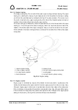
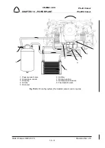
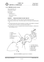
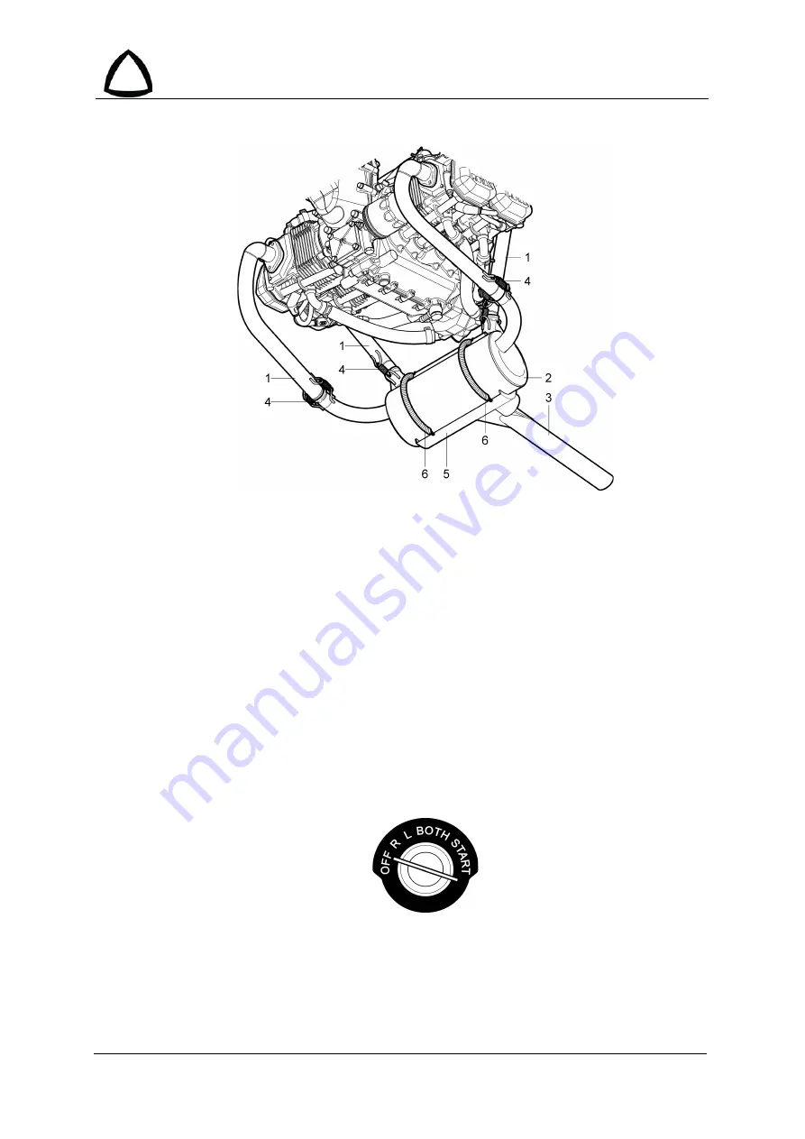
1 Exhaust tube
4 Spring
2 Muffler
5 Heat exchanger
3 Outlet exhaust tube
6 Spring
Fig. 10-6
: Exhaust system
10.2.1.9 Ignition system
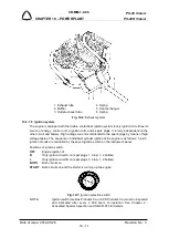
The engine is equipped with the double contactless ignition system. Every ignition circuit has its
source of energy, control unit, 2-ignition coils and 4-spark plugs. It is fully independent on the
other circuit and battery. High voltage current is distributed to the spark plugs by means of high
voltage cables. The sequence of individual cylinder ignition of the engine is as follows: 1-4-2-3.
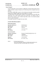
Ignition circuits are controlled by the keyed ignition switch on the instrument panel.
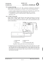
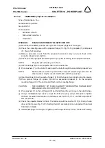
Positions of ignition switch:
OFF
Engine ignition of
R
Only ignition circuit A on (spar plugs 1, 2 top; 3, 4 bottom)
L
Only ignition circuit B on (spar plugs 3, 4 top; 1, 2 bottom)
BOTH
Both circuits on
START
Both circuits on and the starter is running up the engine
Fig. 10-7
: Ignition selection switch
NOTE:
Ignition switch (Gerdes Products Co. or ACS Products Co.) must be inspected
and lubricated after every 2 000 hours of operation. See Chapter 2 -
Scheduled Special Inspection and SB-CR-073 for details.

