PS-28 Cruiser
PS-28N Cruiser
CR-MM-1-0-00
CHAPTER 11 – ELECTRICAL SYSTEM
Revision No.: 25
Date of issue: 2021-01-15
11 - 8
11.2.3 Fuses
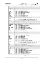
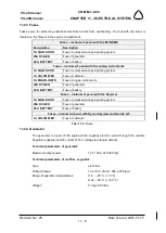
Fuses serve for protecting individual electrical circuits from overloading. The box with the fuses is
located on the firewall in the engine compartment.
Fuses – instrument panel with the EFIS/EMS
Designation
Description
1A SIGN. DOOR
Fuse of unlocked canopy signaling system
25A DC GEN
Fuse of generator
25 A BATTERY
Fuse of battery
Fuses – instrument panel with the analog instruments
1A SIGN. DOOR
Fuse of unlocked canopy signaling system
1A VOLTMETER
Fuse of voltmeter
1A ENGIN. INSTR.
Fuse of engine instruments
25A DC GEN
Fuse of generator
25 A BATTERY
Fuse of battery
Fuses – instrument panel with the Skyview
1A SIGN. DOOR
Fuse of unlocked canopy signaling system
25A DC GEN
Fuse of generator
25 A BATTERY
Fuse of battery
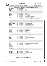
Fuses – instrument panel with Dynon Skyview and Garmin G5
1A VOLTMETER
Fuse of voltmeter
Tab. 11-3
: Fuses
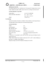
11.2.4 Generator
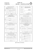
The generator is a part of the engine which supplies electric current through the rectifier.
Regulator supplies electric current of 14 V voltage to onboard network.
Technical parameters of generator:
Maximum output power:
12 V / 20 A
at 5,000 rpm
Technical parameters of rectifier - regulator:
Type:
electronic
Output voltage:
14 ± 0.3 V (from 1,000 ± 250 rpm)
Range of operation temperatures:
min. – 25 °C (
- 13 °F
)
max. + 90 °C (
+ 194 °F
)
Weight:
0.3 kg (
0.66 lbs
)

