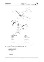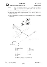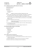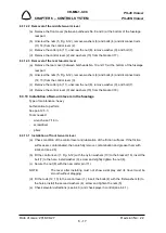
background image

PS-28 Cruiser 

PS-28N Cruiser 

CR-MM-1-0-00 


CHAPTER 6 – CONTROL SYSTEM 


Revision No.: 2 


Date of issue: 2011-11-08 

6 - 24


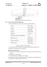
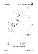
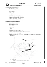
Adjusting aileron deflections 

a)  Aileron deflections up and down (different) are adjusted at the manufacturer. 

b)  For re-adjustment of the aileron neutral position: 

-

  Set control sticks to neutral position; 

-

  Through the adjustment of the end piece of the end control rod - set the left aileron to 

the neutral position. 

-

  Through the adjustment of the end piece of the end control rod - set the right aileron to 

the neutral position. 

c)  Adjust the range of deflections (if applicable) through the stops at control sticks.  

Adjusting wing flap deflections 

Wing flap deflections are given by the torque tube and actuator positioning in the fuselage. It is 

not possible to adjust flap deflection outside manufacturing company. 

Adjust flap deflections through eccentric parts of pins. 

Adjusting elevator deflections 

Range of elevator deflections is given by setting the push rod terminals in the fuselage. At 

adjusting elevator deflections, proceed as follows: 

a)  Remove the chosen push rod from the bell crank. 

b)  Adjust the upper deflection as needed by means of the push rod terminal (or by means of 

push rod terminal on the elevator lever). 

c)  Put push rod end back and check if the deflections corresponds to the values mentioned in 

the Tab. 6-1. 

Adjusting rudder deflections 

Rudder deflections are given by setting the stops on the rudder control lever installed on root 

rudder rib. 

a)  Set the foot control pedals to neutral position and check if the rudder is in the neutral position. 

b)  Carry out correction of rudder  deflection setting by adjusting the turnbuckles on the foot 

pedal side in cockpit. 

Adjusting trim tab deflections 

Trim tab deflections are given by control actuator and they are fixed. 


6.4.5  Checking condition of rudder control cables. 

a)  Carefully inspect the control cable especially on the following areas: 


in the area of cable attachment on the rudder control pedals 


in the area of cable attachment on rudder lever 


in the area of cable inlet on rear fuselage 

b)  Check for the following defects on the cable: 


burst cable wires 
Summary of Contents for CRUISER AIRCRAFT PS-28 Cruiser 2021

Page 1: ...01 15 Revision No 25 i This document is prepared in accordance with the AP DOA Approval No AP 507 PS 28 Cruiser PS 28N Cruiser MAINTENANCE MANUAL Copy No This document contains EASA approved Chapter 2A Airworthiness Limitation Section ...

Page 2: ...CR MM 1 0 00 Revision No 25 Date of issue 2021 01 15 ii INTENTIONALLY LEFT BLANK ...

Page 3: ...28 Cruiser PS 28N Cruiser MAINTENANCE MANUAL PS 28 Cruiser and PS 28N Cruiser aircrafts are designed and manufactured by Czech Aircraft Group s r o Na Záhonech 212 686 04 Kunovice Czech Republic Website www cruiseraircraft cz E mail info cruiseraircraft cz This document contains EASA approved Chapter 2A Airworthiness Limitation Section ...

Page 4: ...CR MM 1 0 00 Revision No 25 Date of issue 2021 01 15 iv INTENTIONALLY LEFT BLANK ...

Page 5: ...ion and maintenance practices i to iv 0 1 0 6 to 0 9 1 1 1 3 to 1 6 1 8 1 9 2 1 to 2 16 4 6 4 7 6 27 7 1 to 7 12 8 1 8 12 to 8 15 8 17 to 8 23 9 1 9 5 9 8 9 12 10 1 to 10 40 11 2 11 6 11 7 11 11 11 12 12 1 to 12 30 2011 07 08 2011 07 08 Konečný 2 Specification of engines marking supplementation of chapters Equipment List Sources to Purchase Parts List of Disposable Replacement Parts Weight and Bal...

Page 6: ...harnesses supplementation of the third friction washer on nose gear leg supplementation of fuel scheme modification of the fuel system tightness check correction of Rotax manuals section torque moment and exhaust installation correction of engine test report supplementation of Klassic 170 3 R propeller inspections supplementation of SkyView system switches circuit breakers supplementation of SkyVi...

Page 7: ...0047966 31 1 2014 9 Correction of cross reference supplementation of improved nose landing gear and modification of relevant maintenance practices i to iv 0 3 0 6 0 7 2 5 2 7 2 11 2 12 8 4 8 5 8 19 2014 02 17 EASA Minor Change Approval 10048185 18 2 2014 10 Supplementation of balance ballast description and installation i to iv 0 3 0 6 3 1 3 5 3 10 3 11 2014 08 22 EASA Minor Change Approval 100503...

Page 8: ...m S N 0571 i to iv 0 4 0 6 0 8 11 5 11 6 2016 08 17 EASA Minor Change Approval 10059451 16 9 2016 18 Dual Circuit Thermostat Hektik F1107 in the PS 28 Cruiser Engine Liquid Cooling System i to iv 0 4 0 8 10 1 10 2 10 6 10 7 10 47 2016 10 24 EASA Major Change Approval 10060546 21 12 2016 19 Installation of ELT Kannad 406 AF Compact in Airplanes with Analog Equipment i to iv 0 4 0 6 0 7 7 1 7 3 7 10...

Page 9: ... Gerdes or ACS ignition switches i to iv 0 5 0 6 0 8 0 9 2 8 12 2 12 62 to 12 66 2020 01 15 EASA Minor Change Approval 10072846 18 03 2020 24 Airworthiness Limitation Section ALS integration i to iv 0 5 0 6 0 7 0 8 0 10 1 1 1 4 1 7 1 8 1 10 1 11 1 12 1 13 1 14 2 1 2 2 2 3 2 4 2 5 2 6 2 7 2 8 2 9 2 10 2 11 2 12 2 13 2 14 2 15 2 16 2 17 2 18 2 19 2 20 3 1 3 5 3 6 3 12 6 2 7 3 7 7 7 9 9 3 9 5 10 1 10...

Page 10: ... 3 2011 03 08 0 9 2021 01 15 3 4 2012 12 10 0 10 2020 11 19 3 5 2020 11 19 3 6 2020 11 19 3 7 2011 03 08 1 1 1 2020 11 19 3 8 2011 11 08 1 2 2011 03 08 3 9 2011 03 08 1 3 2017 12 05 3 10 2018 09 27 1 4 2020 11 19 3 11 2014 08 22 1 5 2021 01 15 3 12 2020 11 19 1 6 2021 01 15 1 7 2020 11 19 1 8 2020 11 19 4 4 1 2018 09 27 1 9 2011 07 08 4 2 2011 03 08 1 10 2020 11 19 4 3 2011 03 08 1 11 2020 11 19 4...

Page 11: ... 01 15 6 3 2011 03 08 6 4 2011 03 08 8 8 1 2018 09 27 6 5 2021 01 15 8 2 2011 03 08 6 6 2018 09 27 8 3 2018 09 27 6 7 2018 09 27 8 4 2014 02 17 6 8 2011 03 08 8 5 2014 02 17 6 9 2018 09 27 8 6 2011 03 08 6 10 2018 09 27 8 7 2018 09 27 6 11 2018 09 27 8 8 2018 09 27 6 12 2018 09 27 8 9 2018 09 27 6 13 2018 09 27 8 10 2011 03 08 6 14 2018 09 27 8 11 2011 03 08 6 15 2011 03 08 8 12 2018 09 27 6 16 20...

Page 12: ... 10 42 2017 12 05 10 43 2020 11 19 10 10 1 2021 01 15 10 45 2017 12 05 10 2 2021 01 15 10 46 2017 12 05 10 3 2015 09 23 10 4 2015 09 23 11 11 1 2021 01 15 10 5 2015 09 23 11 2 2011 07 08 10 6 2021 01 15 11 3 2011 03 08 10 7 2021 01 15 11 4 2017 12 05 10 8 2011 07 08 11 5 2021 01 15 10 9 2021 01 15 11 6 2017 12 05 10 10 2014 01 30 11 7 2021 01 15 10 11 2012 05 28 11 8 2021 01 15 10 12 2020 11 19 11...

Page 13: ... 2014 10 29 12 57 2021 01 15 12 16 2015 09 23 12 58 2018 09 27 12 17 2014 10 29 12 59 2021 01 15 12 18 2015 09 23 12 60 2012 12 10 12 19 2014 10 29 12 61 2021 01 15 12 20 2021 01 15 12 62 2021 01 15 12 21 2021 01 15 12 63 2014 10 29 12 22 2021 01 15 12 64 2014 10 29 12 23 2018 09 27 12 65 2014 10 29 12 24 2021 01 15 12 66 2014 10 29 12 25 2021 01 15 12 67 2014 10 29 12 26 2018 09 27 12 68 2014 10 ...

Page 14: ...3 10 2013 01 11 17 6 2012 12 10 17 7 2012 12 10 17 8 2012 12 10 14 14 1 2011 03 08 14 2 2011 03 08 14 3 2011 03 08 18 18 1 2011 03 08 14 4 2011 03 08 18 2 2011 03 08 18 3 2011 03 08 18 4 2011 03 08 15 15 1 2011 07 08 15 2 2011 03 08 15 3 2011 03 08 15 4 2011 03 08 15 5 2011 03 08 15 6 2011 03 08 15 7 2011 03 08 15 8 2011 03 08 15 9 2011 03 08 15 10 2011 03 08 15 11 2011 03 08 15 12 2011 03 08 15 1...

Page 15: ...TER 3 FUSELAGE 3 1 CHAPTER 4 WING 4 1 CHAPTER 5 TAIL UNIT 5 1 CHAPTER 6 CONTROL SYSTEM 6 1 CHAPTER 7 EQUIPMENT 7 1 CHAPTER 8 LANDING GEAR 8 1 CHAPTER 9 FUEL SYSTEM 9 1 CHAPTER 10 POWERPLANT 10 1 CHAPTER 11 ELECTRICAL SYSTEM 11 1 CHAPTER 12 INSTRUMENTS AND AVIONICS 12 1 CHAPTER 13 VENTING HEATING 13 1 CHAPTER 14 AIRPLANE HANDLING 14 1 CHAPTER 15 AIRPLANE REPAIRS 15 1 CHAPTER 16 WIRING DIAGRAMS 16 1...

Page 16: ...PS 28 Cruiser PS 28N Cruiser CR MM 1 0 00 CHAPTER 1 GENERAL Revision No Date of issue 2011 03 08 1 2 INTENTIONALLY LEFT BLANK ...

Page 17: ...rer and Type Certificate Holder 1 7 1 4 Chapter Order 1 7 1 4 1 Page Numbering 1 7 1 5 Warnings Cautions and Notes 1 7 1 6 Equipment List 1 8 1 7 Sources to Purchase Parts 1 8 1 8 List of Disposable Replacement Parts 1 8 1 9 Weight and Balance Information 1 8 1 10 Tire Inflation Pressure 1 8 1 11 Approved Oils and Capacities 1 8 1 12 Recommended Fastener Torque Values 1 8 1 13 General Safety Infor...

Page 18: ...ype 912 Series Maintenance Manual for ROTAX Engine Type 912 Series Technical description and operation instructions for the propeller This Maintenance Manual contains information on airplane maintenance including description of airplane structure and function 1 2 Airplane Classification PS 28 Cruiser airplane is two seat single engine low wing all metal airplane with fixed three wheel landing gear...

Page 19: ... m2 7 00 sq ft Fuselage Length 6 680 m 21 91 ft Width 1 280 m 50 40 in Height 2 340 m 7 67 ft Cockpit width 1 170 m 46 00 in Horizontal tail unit Span 2 930 m 9 61 ft HTU area 2 2 m2 23 70 sq ft Elevator area 0 8 m2 8 60 sq ft Vertical tail unit Height 1 07 m 3 51 ft VTU area 1 m2 10 70 sq ft Rudder area 0 4 m2 4 30 sq ft Landing gear Wheel track 1 520 m 4 98 ft Wheel base 2 030 m 6 66 ft Nose lan...

Page 20: ...PS 28 Cruiser PS 28N Cruiser CR MM 1 0 00 CHAPTER 1 GENERAL Revision No 25 Date of issue 2021 01 15 1 6 Fig 1 1 Three view drawing ...

Page 21: ...g sequence from No 1 Every chapter describes one system or assembly 1 4 1 Page Numbering Example 1 5 Warnings Cautions and Notes WARNING MEANS THAT NON OBSERVATION OF THE CORRESPONDING OPERATING INSTRUCTION INSPECTION OR MAINTENANCE PROCEDURE CAN LEAD TO INJURY OR DEATH OF PERSONS CAUTION MEANS THAT NON OBSERVATION OF THE CORRESPONDING OPERATING INSTRUCTION INSPECTION OR MAINTENANCE PROCEDURE CAN ...

Page 22: ...arts Store Oil filter 825701 825012 825016 Czech Aircraft Group BRP Powertrain Tire and tube Goodyear Flight Special II 5 00 5 Czech Aircraft Group Aircraft Parts Store Brake lining WHLM66 106 Czech Aircraft Group Aircraft Parts Store 1 9 Weight and Balance Information Refer to PS 28 Cruiser Pilot s Operating Handbook Section 6 for the Weight and Balance Data 1 10 Tire Inflation Pressure Refer to ...

Page 23: ...ivating the BRS rocket if installed Never leave the ignition switch or the master switch turned on when the engine is not running While running the engine on the ground keep away from the propeller Remove any loose clothing such as neckties and scarves Tuck in your shirt and secure any long hair to prevent them from becoming tangled in power tools Remove all jewelry Not only can items such as ring...

Page 24: ...ructions provided in the maintenance manual supplied with the aircraft The purpose of the inspection is to look for any wear corrosion or damage that would cause an aircraft to not be in a condition for safe operation ATC Air Traffic Control bar Pressure unit 1 bar 14 5037 psi BEACON Anti collision beacon BRS Ballistic Recovery System CAG Czech Aircraft Group s r o CAS Calibrated Airspeed COMM Com...

Page 25: ...epairman Inspection U S FAA certificated repairman light sport aircraft with an inspection rating defined by 14 CFR Part 65 authorized to perform the annual condition inspection on experimental light sport aircraft or an equivalent rating issued by other civil aviation authorities LSA Repairman Maintenance U S FAA certificated repairman light sport aircraft with a maintenance rating as defined by ...

Page 26: ...trol element is in on position OVERHAUL maintenance inspection repair or alterations that are only to be accomplished by the original manufacturer or a facility approved by the original manufacturer of the product POH Pilot Operating Handbook psi Pressure unit pounds per square inch 1 psi 0 0689 bar RoR Record of Revisions rpm revolutions per minute sec second SM Statute Mile 1 SM 1 609 m TSN Time...

Page 27: ...CR MM 1 0 00 PS 28 Cruiser PS 28N Cruiser CHAPTER 1 GENERAL Date of issue 2020 11 19 Revision No 24 1 13 VTU Vertical Tail Unit XPDR Secondary radar transponder ...

Page 28: ...PS 28 Cruiser PS 28N Cruiser CR MM 1 0 00 CHAPTER 1 GENERAL Revision No 24 Date of issue 2020 11 19 1 14 INTENTIONALLY LEFT BLANK ...

Page 29: ... 3 2B 1 Overhaul Schedule 2 3 2B 2 Periodic Inspection Schedule 2 3 2B 3 Replacement Schedule 2 3 2B 4 Scheduled Maintenance 2 4 2B 4 1 General 2 4 2B 4 2 Tables of inspection tasks 2 5 2B 4 3 Special Inspection after first 5 and 25 operating hours 2 5 2B 4 4 Scheduled Inspection after 50 FH or OH 2 6 2B 4 5 Scheduled Annual Periodical Inspection API or Inspection after 100 FH or OH 2 7 2B 4 6 Sch...

Page 30: ...5 years 2A 5 Propeller Life Limitation None 2A 6 Other Components Life Limitation ITEM INTERVAL PROCEDURE NOTE 1 Fuel pump 5 years REPLACE 2 Engine rubber parts 5 years REPLACE According to the Rotax Maintenance Manual 3 Flexible fuel system hoses 5 years REPLACE 4 Flexible oil system hoses 5 years REPLACE 5 Flexible cooling system hoses 5 years REPLACE 6 V belt 5 years REPLACE 7 Battery 5 years o...

Page 31: ... operation or 12 months whichever comes first and after every new propeller installation See also last instructions issued by the propeller manufacturer www woodcomp cz 2B 2 Periodic Inspection Schedule ITEM INTERVAL PROCEDURE NOTE 1 Sensenich 3B0R5R68C propeller 2 000 OH PERIODIC INSPECTION No specified overhaul time The propeller parts are removed from service when they can no longer meet the Co...

Page 32: ...G 100 H INSPECTION MUST BE PERFORMED AT THE LATEST AFTER 187 H a Preflight inspection is performed within the scope given in the POH Section 4 b Scheduled special propeller inspection after 25 50 and 150 OH see Installation and Operating Instructions for installed propeller NOTE To be performed with a newly installed propeller or with the propeller that was dismantled and reinstalled on the airpla...

Page 33: ...RS Aircraft S N TSN OH Registration mark TSN cycles Page 1 of 1 Chpt Prescribed works Made by Checked by 10 Engine and propeller List of performed operations for engine is shown in Maintenance Manual Line Maintenance for ROTAX Engine Type 912 Series MML 912 Remove and check engine cowlings for evident signs of heat damage or cracks Inspect and check tightening and securing bolts on the engine brac...

Page 34: ...ks delamination or other damage FH Check attachment of the wheel axis FH Check securing of nuts FH Check visually using mirror the condition and wearing of brake pads minimum admissible thickness of brake pad is 2 5 mm and brake disc FH Nose Landing Gear Check of the landing gear leg for cracks valid for reinforced NLG No SG0300N FH 10 Engine Remove and check engine cowlings for evident signs of h...

Page 35: ...ervals Both FH Check that the replacement or overhaul of life limited parts parts related to engine and propeller has been in accordance to their specified intervals Both OH Assure that replacements of the parts excluding engine and propeller are performed in appropriate intervals Both FH Assure that replacements of the parts related to engine and propeller are performed in appropriate intervals B...

Page 36: ...th FH Check condition and attachment of the canopy frame Both FH Check condition of the canopy plexiglass and fixed windows scratches cracks silvering Both FH Check condition and function of canopy gas struts Both FH Check attachment and function of the sunshield Both FH Check condition of the canopy control including canopy lock Both FH Check condition and adjustment of terminal switches Both FH ...

Page 37: ... securing Both FH Check elevator attachment and securing Both FH Check condition and attachment of elevator tips Both FH Check free travel of the elevator Both FH Check condition of stop elevator fully deflected down Both FH Check condition and attachment of the trim tab Both FH Check trim tab actuator connector for connection and securing Both FH Check condition and attachment of the balance tab ...

Page 38: ...Check adjustment of pedals and full deflections in all position Both FH Flaps Control Check for free travel of the control lever Both FH Check securing of links Both FH Check condition of control actuator and position indicator Both FH Control of the Pitch and Roll Trim Tab Check condition of the control actuators and position indicators Both FH Check plays see 6 4 1 Both FH Check securing of link...

Page 39: ... Both FH Check visually using mirror condition and wearing of brake pads and brake disc Min admissible thickness of brake pad is 2 5 mm 0 1 in min admissible thickness of brake disc is 4 25 mm 0 167 in Both FH Check brake fluid leakage brake fluid hoses brake pumps brake cylinders Replenish brake fluid as needed see 8 5 4 Both FH Exchange brake fluid applied for annual inspection only see 8 5 4 AP...

Page 40: ...th OH 10 Engine and Propeller List of performed operations for engine is shown in Maintenance Manual Line Maintenance for ROTAX Engine Type 912 Series MML 912 Both OH List of performed operations for the propeller is shown in Installation and Operating Instructions for installed propeller See also 10 4 2 2 or 10 4 4 1 as applicable Both OH Remove and check engine cowlings for evident signs of heat...

Page 41: ...hment of instruments Both FH Check condition and attachment of the pitot tube Both FH Check cleanness of air inlet holes of pitot tube Both FH Check attachment and securing of hoses to the instruments Both FH Check for pitot static system tightness see 12 4 1 with 2 years periodicity 2 yr FH Visually check condition of navigation and communication instruments Both FH Perform compensation of magnet...

Page 42: ...ators including signalization Both FH Check function of navigation and communication instruments in accordance with all valid and applicable regulations applied for annual inspection only API FH ELT perform a functional test according to the applicable regulations Both FH Check function of the signaling warning lights Both FH Check all instruments for their function Both FH Close up Tasks Lubricat...

Page 43: ...r Inspection after 500 hrs of operation or 36 months Remove the propeller and send it to the manufacturer authorized service organization checking of propeller after 500 hrs is done at manufacturer or his authorized service organization Inspection after 1 000 hrs of operation or 72 months Remove the propeller and send it to the manufacturer authorized service organization checking of propeller aft...

Page 44: ...ganization checking of propeller after 2000 hrs is done at manufacturer or his authorized service organization 12 Ignition switch inspection and lubrication after every 2000 hours of operation For detail work procedure see section 12 4 10 Notes Date Signature 2B 4 7 Scheduled Inspection after 25 FH or 50 cycles SCHEDULED INSPECTION AFTER 25 FH or 50 cycles whichever comes first Aircraft S N TSN OH...

Page 45: ... and personnel involved in these tasks 2B 5 Lubrication chart 2B 5 1 Lubrication chart depending on the OH Unit Area of lubrication After first 25 OH Every 100 OH Every 500 OH Lubricant Engine Throttle control cable on the inlet into terminal in the engine compartment X X X LPS1 Choke control cable on the inlet into terminal in the engine compartment X X X LPS1 2B 5 2 Lubrication chart depending o...

Page 46: ...ry 100 FH Every 500 FH Lubricant Main Landing Gear Brake pad pins X X X LPS3 Ailerons Hinges X X X AeroShell Grease 22 Rod end bearing of the control tubes X AeroShell Grease 22 Two arm control levers in the fuselage X AeroShell Grease 22 Bell cranks in the wings X AeroShell Grease 22 Flaps Hinges X X X AeroShell Grease 22 Rod end bearings on actuator X AeroShell Grease 22 ...

Page 47: ...very 500 FH Lubricant HTU Elevator hinges X X X AeroShell Grease 22 Rod end bearing of the elevator control tubes X AeroShell Grease 22 Pins front stabilizer hinge Annual insp LPS3 VTU Rudder hinges X X X AeroShell Grease 22 Cable shackles on the rudder control cables X X X AeroShell Grease 22 Trim and balance tabs Tabs hinges X X X LPS1 Rod end on actuators X X X AeroShell Grease 22 ...

Page 48: ...ks in the cockpit X AeroShell Grease 22 Rudder control All movable links in the cockpit X AeroShell Grease 22 Cable shackles of rudder control X X AeroShell Grease 22 2B 6 Ordering spare parts Order spare parts through the Airplane failures card see Section 17 4 NOTE Spare parts for the engine shall be provided with EASA Form One issued by Rotax or CAG unless they are identified as a standard part...

Page 49: ...Canopy 3 5 3 2 5 2 Rear fixed canopy windows 3 5 3 2 6 INTENTIONALLY LEFT EMPTY 3 5 3 2 7 BaIance ballast 3 5 3 3 Removal Installation 3 7 3 3 1 Canopy removal 3 7 3 3 2 Canopy installation 3 7 3 3 3 Gas strut removal 3 8 3 3 4 Gas strut installation 3 9 3 3 5 Cabin lock removal 3 9 3 3 6 Cabin lock installation 3 10 3 3 7 Balance ballast installation 3 10 3 4 Check Adjustment 3 12 3 4 1 Canopy lo...

Page 50: ...from the engine compartment Cockpit with fixed seats is located between bulkheads No 1 and 5 The baggage compartment is located behind the seats Center section of wing consists of the main attachments 2 are located between bulkheads No 2 and 3 and the rear attachment 3 which is located on the bulkhead No 5 main landing gear attachment points 4 are located behind main center wing spar the engine mo...

Page 51: ...ith control elements The cockpit is equipped with two fixed seats NOTE Current instrument panel arrangement is stated in the Pilot s Operation Handbook Supplement No 1 The cockpit floor and baggage compartment is covered with a removable carpet and the middle console is covered with thin upholstery The interior cockpit sides are covered with padded panels containing pockets and armrests 1 Nose lan...

Page 52: ... Max baggage weight transported in the baggage compartment is 18 kg 40 lbs 3 2 5 Crew canopy The crew canopy is produced of organic glass and consists of opening canopy and rear fixed canopy windows 1 Canopy 6 Locking lever 2 Canopy hinge 7 Rear canopy window 3 Gas strut 8 Baggage compartment 4 Canopy lock 9 Sunshield 5 Inside opening lever 10 Sliding side ventilation window Fig 3 3 Canopy rear ca...

Page 53: ... 3 3 and sliding ventilation windows located on both sides of the canopy Closing and securing of the canopy is sensed by one terminal switch located at the inside opening lever between the seats see Wiring Manual If the canopy is not properly closed and secured the CABIN OPENED light will be flashed in red on the upper part of the left instrument panel 3 2 5 2 Rear fixed canopy windows The rear fi...

Page 54: ...PS 28 Cruiser PS 28N Cruiser CR MM 1 0 00 CHAPTER 3 FUSELAGE Revision No 24 Date of issue 2020 11 19 3 6 INTENTIONALLY LEFT BLANK ...

Page 55: ... Hold the canopy e Unscrew the nuts 5 remove the washers 6 and the bolts 4 f Carefully remove the canopy 1 and store it in a safe place so that windscreen damage cannot occur 3 3 2 Canopy installation Type of maintenance line Authorization to perform Sport pilot or higher Tools needed Socket wrench size 7 16 screwdriver pliers CAUTION DURING CANOPY INSTALLATION BE CAREFULLY TO AVOID SCRATCHING THE...

Page 56: ...opy removal installation 3 3 3 Gas strut removal Type of maintenance line Authorization to perform Sport pilot or higher Tools needed screwdriver pliers a Open the canopy 5 Fig 3 6 hold it b Remove the safety clip 3 from the ball joint end fittings 2 on the canopy frame 5 and on the fixed frame 6 c Remove the gas strut 1 NOTE Access to the nuts 5 and washers 6 is from the cockpit ...

Page 57: ...r it is not damaged b Insert top ball joint end fitting 2 on the ball stud 4 on the canopy frame 5 and bottom ball joint end fitting 2 on the ball stud 4 on the fixed frame 6 c Secure the joints with safety clips 3 3 3 5 Cabin lock removal Type of maintenance line Authorization to perform Sport pilot or higher Tools needed screwdriver a Unscrew the screw 2 Fig 3 7 attaching the lock 1 to the fusel...

Page 58: ... Type of maintenance line Authorization to perform Sport pilot or higher Tools needed screwdriver a Put the lock 1 Fig 3 7 in to the hole in the fuselage skin b Screw the screw 3 attaching lock to the fuselage skin 3 3 7 Balance ballast installation Type of maintenance heavy Authorization to perform See point 2 5 3 Tools needed wrench size 3 8 7 16 in screwdriver pliers electric drill drill bit 4 ...

Page 59: ...sert to the upper holes of the bulkhead No 13 bolts 6 with washers 8 on the bolts insert balance ballast 1 plate 2 washers 8 screw and tighten nuts 7 e According holes in the plate 2 drill both lower holes f Insert to the lower holes of the bulkhead No 13 bolts 3 with washers 5 on the bolts insert washers 5 screw and tighten nuts 4 g Place the cover 11 and fasten it by bolts 12 h Install the horiz...

Page 60: ...1 19 3 12 3 4 Check Adjustment 3 4 1 Canopy lock adjustment Adjust the locks so that the canopy could be locked freely Set the length of the rod 3 4 2 INTENTIONALLY LEFT EMPTY 3 5 Exchanges Service information 3 5 1 Canopy glass cleaning Canopy glass cannot be cleaned by the alcohol based cleaner ...

Page 61: ... 2 4 2 1 Wing 4 2 4 2 2 Wing flaps 4 3 4 2 3 Ailerons 4 4 4 2 4 Fuel tanks 4 4 4 2 5 Wing lockers 4 5 4 3 Removal Installation 4 5 4 3 1 Wing removal 4 5 4 3 2 Wing installation 4 6 4 3 3 Wing flap removal 4 8 4 3 4 Wing flap installation 4 9 4 3 5 Aileron removal 4 9 4 3 6 Aileron installation 4 10 4 4 Check Adjustment 4 11 4 5 Exchanges Service information 4 11 ...

Page 62: ...lage Fig 3 1 and from outer wings placed between ribs No 1 and 9 which have trapezoid shape Fig 4 1 The wing is of all metal main spar structure with a rear spar In the outer wings are installed between ribs No 4 and 6a leading edge fuel tanks on the aft spar there are hinged ailerons 1 Fig 4 2 and flaps 2 The wing tips 3 made out of fiberglass are riveted on the wing ribs No 9 On wing tips are in...

Page 63: ...ent Fig 4 2 Wing left 4 2 2 Wing flaps Flaps are of all metal structure consisting of the skin 1 Fig 4 3 aluminum sheet metal spar and ribs 2 which are connected by means of riveting Flaps are suspended on the wing aft spar by means of two hinges 4 There is a guiding plate 3 on flap root rib where is connected the flap control pin The flap control actuator is installed in the fuselage behind left ...

Page 64: ...ected by means of riveting Ailerons are suspended on the rear spar by means of two hinges 4 Moreover the trim tab 5 is installed on the right aileron serving the lateral balance of airplane The trim tab actuator is installed inside of aileron Control lever 3 is installed on the root aileron rib Fig 4 4 Aileron right 1 Flap skin 2 Flap rib 3 Guiding plate 4 Flap hinge 1 Aileron skin 2 Aileron rib 3...

Page 65: ... 4 2 5 Wing lockers Wings are equipped with wing locker 7 Fig 4 2 placed between ribs No 4 and 5 behind main spar Capacity of each wing locker is 10 kg 22 lbs Access doors installed on piano hinge are locked per quick fasteners 4 3 Removal Installation 4 3 1 Wing removal Type of maintenance heavy Authorization to perform See point 2 5 3 Tools needed wrench size 7 16 in 1 2 in Phillips PH2 screwdri...

Page 66: ...ization to perform See point 2 5 3 Tools needed wrench size 7 16 in 1 2 in Phillips PH2 screwdriver pliers hammer Install the wing according to the following procedure a Before installation clean the attachments and bolts of the outer and center wing from dirt Preserve bolts and attachments by means of lubricating grease b Set the wing about 300 mm 12 in to the fuselage side The first person will ...

Page 67: ... adjusting of theirs deflections see 6 4 4 l Install access cover plates on the seats floor and access cover on the bottom wing root 1 Wing left 14 Pitot static hose 2 Bolt 6 pcs 15 Hose connector 3 Nut 6 pcs 16 Fuel quantity sensor wiring 4 Washer 10 pcs 17 Aileron trim tab wiring only right side 5 Bolt 18 Position light wiring 6 Nut 19 Front attachment 7 Washer 20 Front attachment 8 Bolt 21 Rear...

Page 68: ...g 4 7 in full position b Unscrew the nuts 5 remove the washers 6 bolts 4 and disconnect both flap hinges remove the washers 7 c Carefully remove the flap 1 from the wing d Store the removed flap on a safe place and prevent it from damage 1 Wing flap 7 Washer 2 Inner flap hinge 8 Wing inner flap hinge 3 Outer flap hinge 9 Wing outer flap hinge 4 Bolt 10 Control pin 5 Nut 11 Rear attachment cover 6 ...

Page 69: ...5 tight the nuts with prescribed tightening moment 5 5 8 Nm 50 70 inch lb e Close the flap in the zero up position f Perform check the wing flaps operation and their deflections see 6 4 3 4 3 5 Aileron removal Type of maintenance heavy Authorization to perform See point 2 5 3 Tools needed wrench size 7 16 in cutting pliers a Disconnect the control rod with control lever b On the right aileron only...

Page 70: ... actuator wires 2 Fig 6 8 going out from wing to the aileron d Insert the bolts 3 Fig 4 8 in to the hinges install the washers 5 and screw the nuts 4 e Connect the control rod 6 with aileron control lever 2 by means of bolt 7 nut 8 and washer 9 f Connect trim tab actuator wires 2 Fig 6 8 close the access hole with cover 10 on the right aileron only see Wiring Manual g Perform check the trim tab op...

Page 71: ...CR MM 1 0 00 PS 28 Cruiser PS 28N Cruiser CHAPTER 4 WING Date of issue 2011 03 08 Revision No 4 11 4 4 Check Adjustment No procedures included 4 5 Exchanges Service information No procedures included ...

Page 72: ...PS 28 Cruiser PS 28N Cruiser CR MM 1 0 00 CHAPTER 4 WING Revision No Date of issue 2011 03 08 4 12 INTENTIONALLY LEFT BLANK ...

Page 73: ... 5 2 4 Rudder 5 5 5 3 Removal Installation 5 6 5 3 1 Horizontal stabilizer removal 5 6 5 3 2 Horizontal stabilizer installation 5 6 5 3 3 Elevator removal 5 8 5 3 4 Elevator installation 5 8 5 3 5 Trim tab removal 5 9 5 3 6 Trim tab installation 5 10 5 3 7 Balance tab removal 5 10 5 3 8 Balance tab installation 5 10 5 3 9 Rudder removal 5 11 5 3 10 Rudder installation 5 11 5 4 Check Adjustment 5 1...

Page 74: ... and aluminum skin Individual parts are assembled by riveting The elevator is attached to the rear spar by means of three hinges 2 3 The horizontal stabilizer is mounted on the fuselage by means of front and rear attachments The front attachments consist of two pins 5 Fig 5 3 which are riveted on bulkhead No 12 and bushings 4 Fig 5 1 riveted on front stabilizer spar The rear attachments consist of...

Page 75: ... Mass balances 6 are riveted at the both elevator ends and covered composite tips 7 The elevator is equipped with the trim 2 and balance 3 tabs both are hinged by means of the piano hinge on the rear spar close to the trailing edge of the elevator The balance tab 3 is interconnected by means of the rod with the hinge 5 Fig 5 1 on the stabilizer The tabs are made of aluminum sheet Fig 5 2 Elevator ...

Page 76: ... an integral part with the rear part of the fuselage The fin consists of stiffeners spar ribs and aluminum skin Individual parts are assembled by riveting The fin tip 4 is made of fiberglass On the spar are two rudder hinges lower one 3 and upper one 2 1 Fin 4 Fin tip 2 Rudder upper hinge 5 Pin front stabilizer hinge 3 Rudder lower hinge 6 Rear stabilizer hinge Fig 5 3 Fin ...

Page 77: ... consists of spar ribs and aluminum skin Individual parts are assembled by riveting On the spar are two attachments lower one 3 and upper one 2 for the rudder suspension on the fin Control lever 4 is riveted on root rib On the trailing edge is riveted fixed trim tab 6 Fig 5 4 Rudder 1 Rudder 2 Upper hinge 3 Lower hinge 4 Control lever 5 Rudder tip 6 Fixed trim tab ...

Page 78: ...udder g Carefully pull out the stabilizer 1 in horizontal direction of the attachments and store it in such a way that a damage cannot occur 5 3 2 Horizontal stabilizer installation Type of maintenance heavy Authorization to perform See point 2 5 3 Tools needed wrench size 7 16 in screwdriver pliers NOTE For stabilizer installation three persons are requested a Clean all attachments and apply lubr...

Page 79: ...or deflections see 6 4 4 1 Stabilizer 14 Nut 2 Elevator 15 Washer 3 Rear cover 16 Bolt 4 Bolt 17 Elevator control rod 5 Stabilizer fairing 18 Bolt 6 Bolt 19 Nut 7 Pin front stabilizer hinge 20 Washer 8 Rear stabilizer hinge 21 Cover 9 Rear hinge 22 Balance tab control rod 10 Bolt 23 Balance tab rod hinge 11 Nut 24 Pin 12 Washer 25 Washer 13 Bolt 26 Cotter pin Fig 5 5 Stabilizer elevator removal in...

Page 80: ...it in such a way that a damage cannot occur 5 3 4 Elevator installation Type of maintenance heavy Authorization to perform See point 2 5 3 Tools needed wrench size 7 16 in pliers NOTE For elevator installation two persons are requested a Inspect the hinges on the elevator clean them and apply lubricant on them see 2 6 Do the same for the hinges on the stabilizer b Put the elevator 2 Fig 5 5 in all...

Page 81: ...rm See point 2 5 3 Tools needed pliers cutting pliers electric drill drill diam 3 2 mm 1 8 in a Remove cotter pin 5 Fig 5 6 washers 4 pin 3 and disconnect control rod 6 from the trim tab control lever 2 b Drill out the rivets 8 connecting the piano hinge with elevator c Remove the trim tab 1 with piano hinge 7 from elevator 1 Trim tab 7 Piano hinge 2 Control lever 8 Rivet 3 Pin 9 Balance tab 4 Was...

Page 82: ...l Type of maintenance heavy Authorization to perform See point 2 5 3 Tools needed pliers cutting pliers electric drill drill diam 3 2 mm 1 8 in d Remove cotter pin 5 Fig 5 6 washers 4 pin 3 and disconnect control rod 11 from the tab control lever 10 e Drill out the rivets 8 connecting the piano hinge with elevator f Remove the balance tab 9 with piano hinge from elevator 5 3 8 Balance tab installa...

Page 83: ...nge d Carefully remove the rudder and store it in such a way that a damage cannot occur 5 3 10 Rudder installation Type of maintenance heavy Authorization to perform See point 2 5 3 Tools needed wrench size 3 8 in 7 16 in NOTE For rudder installation two persons are requested a Inspect the hinges on the rudder clean them and apply lubricant on them see 2 6 Do the same for the hinges on the fin b S...

Page 84: ...ision No 22 Date of issue 2018 09 27 5 12 1 Rudder 6 Bolt 2 Bolt 7 Nut 3 Nut 8 Washer 4 Washer 9 Cotter pin 5 Rudder control cable Fig 5 7 Rudder removal installation 5 4 Check Adjustment No procedures included 5 5 Exchanges Service information No procedures included ...

Page 85: ...m tab control actuator removal 6 10 6 3 7 Trim tab control actuator installation 6 11 6 3 8 Removal of aileron control lever behind the seats 6 12 6 3 9 Installation of aileron control lever behind the seats 6 13 6 3 10 Removal of aileron control bell crank in the wing 6 14 6 3 11 Installation of aileron control bell crank in the wing 6 16 6 3 12 Removal of two arm levers in the fuselage 6 16 6 3 ...

Page 86: ...ks Movement of control sticks is transferred by two push rods lead from the control stick to the transmission tube which transmits the movement to two push rods installed behind bulkhead No 5 behind the seats These two push rods lead to the control levers installed in the fuselage Deflection from the control lever is transferred by means of the push rods to the bell crank installed on rear rib No ...

Page 87: ...ge to the elevator Push rods have adjustable terminals with spherical bearings on the ends enabling elevator deflection adjustment Fig 6 2 Longitudinal control scheme 6 2 3 Directional control The rudder control is controlled by means of foot control pedals Pedal deflections of foot control are transferred by means of steel cables to the rudder Steel cables are lead through middle channel of the f...

Page 88: ...tor and aileron trim tab control The elevator and aileron trim tabs are controlled by the electrical actuators installed in elevator right aileron and connected per threaded rod with trim tab Control switches are integrated part of grips Trim tabs position is displayed either on the two separate indicators or on the EFIS Fig 6 4 Trim tabs control scheme ...

Page 89: ... by a rocker switch or three position controller Rocker switch has a LED position indicator with positions FLAPS DOWN FLAPS UP on the middle channel under instrument panel It is possible to set the wing flaps to whatever position from 0 to 30 Three position controller Fig 6 6 is located on the middle channel under instrument panel It is a three position controller with fixed positions of flaps see...

Page 90: ...Do not rinse bearings and articulated joints with technical gasoline Mechanically remove contaminated lubricant grease carefully and refill the clean one Orientation of bolts and cotter pins Put the bolts to the joint on the basis of top down rule or From the front to the back with regard to the flight direction This rule decreases possibility of spontaneous bolt falling out of the clamp joint in ...

Page 91: ...pliers a Put the stick 2 Fig 6 7 in the transmission tube 1 b Turn the stick 2 90 degree and insert the bolt 20 with the washer 22 into the transmission tube 1 and stick 2 insert the washers 22 screw and carefully tighten the nut 21 c Secure the nut 21 with the new cotter pin 23 d Put the control stick assembly with the washers 17 between the brackets 25 e Insert the bolts 12 into the holes insert...

Page 92: ...n tube 14 Washer 2 Control stick 15 Nylon washer 3 Grip 16 Cotter pin 4 Aileron control rod 17 Nut 5 Bolt 18 Washer 6 Nut 19 Case 7 Washer 20 Bolt 8 Nut 21 Nut 9 Washer 22 Washer 10 Case 23 Cotter pin 11 Lever 24 Electrical wires 12 Bolt 25 Bracket 13 Nut 26 Elevator control rod Fig 6 7 Control stick removal installation ...

Page 93: ...pen the cover behind the left seat on the floor of baggage space c Disconnect flap actuator wire 2 Fig 6 8 d Remove the cotter pin 9 unscrew the nut 7 remove the washer 8 bolt 6 and disconnect flap arm 11 from the flap actuator 1 e Unscrew the nut 4 remove the washer 5 bolt 3 and disconnect actuator 1 from the actuator hinge 10 f Remove the flap actuator 1 Fig 6 8 Flap control actuator removal ins...

Page 94: ...operation and deflections see 6 4 3 f Install the cover on the floor of baggage space 6 3 6 Trim tab control actuator removal Type of maintenance heavy Authorization to perform See point 2 5 3 Tools needed wrench size No 5 screwdriver cutting pliers pliers electric drill drill diam 3 2 mm 1 8 in NOTE The trim tab control actuator is located in the elevator and the right aileron a Drill out the riv...

Page 95: ... the new cotter pin 9 b Insert the trim tab actuator 1 into the elevator or aileron through access hole and fit in place c Insert the screws 3 into the holes insert the washers 5 screw and carefully tighten the nuts 4 d Fit the rod 6 to the control lever 12 insert pin 7 with washer 8 into the hole insert the washer 5 and secure with the new cotter pin 9 e Connect the actuator wires 3 see Wiring Ma...

Page 96: ...actuator removal installation 6 3 8 Removal of aileron control lever behind the seats Type of maintenance heavy Authorization to perform See point 2 5 3 Tools needed wrench size 7 16 in a Tilt the seat backs b Unscrew the nuts 3 6 Fig 6 10 remove washers 4 7 and bolts 2 5 and disconnect rods 13 14 from the control lever 1 c Remove the cotter pin 12 unscrew the nut 9 remove washer 10 and bolt 8 d R...

Page 97: ...grease them with lubricant see 2 6 b Fit the control lever 1 Fig 6 10 with the nylon washers 11 to the bracket 15 insert the bolt 8 to the hole install washer 10 screw and slightly tighten the nut 9 c Secure the nut 9 with the new cotter pin 12 NOTE The control lever must not show axial play after installing and its travel must be continuous without dragging d Fit the rods 13 14 to the control lev...

Page 98: ...ylon washer 4 Washer 12 Cotter pin 5 Bolt 13 Control rod I 6 Nut 14 Control rod II 7 Washer For information 8 Bolt 15 Bracket Fig 6 10 Aileron control lever behind the seats removal installation 6 3 10 Removal of aileron control bell crank in the wing Type of maintenance heavy Authorization to perform See point 2 5 3 Tools needed wrench size 7 16 in screwdriver ...

Page 99: ... the screws 13 Fig 6 11 and remove the cover 12 b Unscrew the nuts 8 remove the washers 4 bolts 7 and disconnect the rods 9 10 from the bell crank 1 c Remove the cotter pin 6 unscrew the nut 3 remove the washers 4 5 bolt 2 and the bell crank 1 1 Aileron bell crank 8 Nut 2 Bolt 9 Control rod I 3 Nut 10 Control rod II 4 Washer 11 Bracket 5 Nylon washer 12 Cover 6 Cotter pin 13 Screw 7 Bolt Fig 6 11 ...

Page 100: ... and slightly tighten the nut 3 c Secure the nut 3 with the new cotter pin 6 NOTE The bell crank must not show axial play after installing and its travel must be continuous without dragging d Fit the rods 9 10 to the bell crank insert the bolts 7 to the holes install the washers 4 screw and tighten the nuts 8 e Check aileron deflections see 6 4 3 and check plays in control see 6 4 1 6 3 12 Removal...

Page 101: ...move the control lever 3 and washers 10 from the bracket 18 6 3 13 Installation of two arm levers in the fuselage Type of maintenance heavy Authorization to perform See point 2 5 3 Tools needed wrench size 7 16 in screwdriver pliers 6 3 13 1 Installation of front two arm lever a Check condition of the control lever and lubrication of the friction surfaces If the friction surfaces are contaminated ...

Page 102: ...washers 6 to the holes install the second washers 6 screw and tighten the nuts 5 e Check elevator deflections see 6 4 3 and check plays in control see 6 4 1 6 3 13 3 Installation of rear two arm lever a Check condition of the control lever and lubrication of the friction surfaces If the friction surfaces are contaminated then carefully remove contamination and grease them with lubricant see 2 6 b ...

Page 103: ... lever 11 Cotter pin 2 Middle two arm lever 12 Front control rod I 3 Rear two arm lever 13 Front control rod II 4 Bolt 14 Middle control rod 5 Nut 15 Rear control rod 6 Washer For information 7 Bolt 16 Front bracket 8 Nut 17 Middle bracket 9 Washer 18 Rear bracket 10 Nylon washer Fig 6 12 Two arm levers removal installation ...

Page 104: ...HEN ELIMINATE THE CAUSE OF IT AND REPEAT MEASURING Measuring procedure a Measure all plays three times and write down average values b Perform measuring with the blocked control surfaces Before measuring it is necessary to push down the control surface by hand several times max force of 5 kg 11 lbs in the direction of the control surface deflection so that the control system is unblocked and plays...

Page 105: ...r to individual positions Measure play in wing flap control on the wing flap trailing edge Max play of the wing flap measured on the trailing edge must not exceed 4 8 mm 3 16 in 6 4 2 Check of friction in control system Control system must function smoothly within the whole scope of deflections There must not be excessive friction or hitching in the control system In case of failure detection find...

Page 106: ... 2 up 28 2 down Elevator balance tab 25 2 up 19 2 down Aileron trim tab 20 2 up 20 2 down Tab 6 1 Deflections of control surfaces For measuring deflections use protractor with deflecting pointer that will be attached to an appropriate control surface by means of the clamp Measuring aileron deflections a Attach the protractor with the deflecting pointer on the upper skin of the aileron by means of ...

Page 107: ...ble directly to read the rudder deflection If you do not have this special jig use the alternative procedure a Set the rudder to neutral position b Put the rod to the trailing edge of the rudder and mark the lower margin of the rudder trailing edge c Deflect the rudder to extreme positions and with the rule measure distance from the sign to the lower margin of the rudder trailing edge d Calculate ...

Page 108: ...rod terminals in the fuselage At adjusting elevator deflections proceed as follows a Remove the chosen push rod from the bell crank b Adjust the upper deflection as needed by means of the push rod terminal or by means of push rod terminal on the elevator lever c Put push rod end back and check if the deflections corresponds to the values mentioned in the Tab 6 1 Adjusting rudder deflections Rudder...

Page 109: ...e installing it to the fuselage e Insert the new cable 1 from the rudder side into the fuselage f Set Nicopress sleeve 3 on the cable end in cockpit g Bend the cable end in cockpit around the cable thimble 2 insert the turnbuckle eye 4 to the cable thimble 2 set Nicopress sleeve 3 close to the cable thimble and press Nicopress sleeve by Nicopress pliers see 15 10 h Connect new cable with turnbuckl...

Page 110: ...11 11 08 6 26 1 Control cable 10 Cotter pin 2 Cable thimble 11 Cable shackle 3 Nicopress sleeve 12 Bolt 4 Turnbuckle eye 13 Nut 5 Turnbuckle barrel 14 Washer 6 Turnbuckle fork 15 Cotter pin 7 Bolt For information 8 Nut 16 Rudder pedals 9 Washer 17 Rudder lever Fig 6 17 Rudder control cable exchange ...

Page 111: ... Safety harnesses installation 7 5 7 3 4 BRS parachute removal 7 6 7 3 5 BRS parachute installation 7 8 7 3 6 BRS rocket removal 7 8 7 3 7 BRS rocket installation 7 10 7 3 8 ELT antenna removal 7 10 7 3 9 ELT antenna installation 7 11 7 3 10 Antiglare shield removal 7 13 7 3 11 Antiglare shield installation 7 13 7 3 12 Antiglare compass shield removal 7 14 7 3 13 Antiglare compass shield installat...

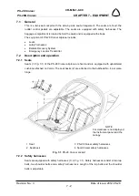
Page 112: ... Emergency Locator Transmitter 7 2 Description and operation 7 2 1 Seats Seats 1 Fig 7 1 of the PS 28 Cruiser airplane are fixed and are equipped with upholstered cushions attached on Velcro The seat backs 2 are attached to the bulkhead No 4 per piano hinge 1 Seat 3 PS 28 Cruiser safety harnesses 2 Seat back 4 SportCruiser safety harnesses Fig 7 1 PS 28 Cruiser cockpit 7 2 2 Safety harnesses Seats...

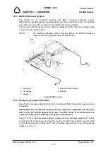
Page 113: ...Emergency Parachute Recovery Systems Doc No 020000 03 1 Parachute 4 Rear attachment cable 2 Harnesses 5 Handle 3 Rocket Fig 7 2 BRS scheme 7 2 4 Emergency Locator Transmitter The aircraft is equipped with the AK 451 ELT or Kannad 406 AF Compact Emergency Locator Transmitter IMPORTANT The AK 451 ELT model produced delivered or fitted after 28 December 2015 is not FAA EASA approved any more That ELT...

Page 114: ...451 Series Doc No IM 451 latest revision or Installation and Operation Manual ELT KANNAD 406 AF COMPACT 406 AF COMPACT ER DOC08038E Revision 04 or later 7 2 5 Antiglare shield With antiglare shield are equipped only VFR airplanes PS 28N Shield serve to prohibition of reflections It is possible to remove the shield by unscrew four screws If airplane will plan to fly at night shield must be installe...

Page 115: ...the shoulder belts bracket 1 from the attachment bracket in baggage compartment b Remove the bolt 3 the bushing 2 and disconnect the lap belt bracket 1 from the attachment point on the fuselage central console side 7 3 3 Safety harnesses installation NOTE Installation of safety harnesses is the same for both safety harnesses models Type of maintenance line Authorization to perform Sport pilot or h...

Page 116: ... Attachment bracket 4 Nut 2 Bushing 5 Washer 3 Bolt Fig 7 4 Safety harnesses removal installation 7 3 4 BRS parachute removal Type of maintenance heavy Authorization to perform See point 2 5 3 Tools needed screwdriver Philips screwdriver wrench size No 7 cutting pliers pliers Allen wrench size 1 8 in 1 4 in ...

Page 117: ...move both instrument panels and disconnect all cable and pitot static connection c Remove COMM NAV equipment from the center panel and disassemble it d Pull open the front flap of the parachute 1 Fig 7 5 and expose the small link unscrew the link nut and disconnect the rocket lanyards 5 e Carefully remove the BRS rocket see 7 3 6 f Cut off cable ties 4 securing link 3 to the tray g Unscrew the lin...

Page 118: ...ant the cover over parachute on the canopy fixed frame f Perform pitot static leak test see Chapter 12 4 1 and check correct function appropriate instruments and systems 7 3 6 BRS rocket removal Type of maintenance heavy Authorization to perform See point 2 5 3 Tools needed screwdriver Philips screwdriver cutting pliers pliers Allen wrench size 1 8 in 1 4 in WARNING UNAUTHORIZED PERSONNEL SHOULD N...

Page 119: ... SO AS TO NOT ACCIDENTLY ACTIVATE ROCKET d Remove screw 7 with 1 8 Allen wrench e Unscrew adapter 4 from rocket Carefully remove housing 3 from rocket by turning entire housing assembly f Loose set screws 10 g Carefully remove the BRS rocket h As necessary remove right side panel of the middle channel unscrew the nut 14 remove the washer 15 bolt 13 and activation housing 3 Fig 7 6 BRS rocket remov...

Page 120: ...e middle channel fasten handle by means of the bolt 13 washer 15 and nut 14 install right side panel of the middle channel c Route the housing in a gentle arc to the base on the rocket The housing cable should have no abrupt bends d Install the rocket e Connect the activation housing to the rocket f Glue by means of the Emfimastic PU 50 sealant the cover over parachute on the canopy fixed frame 7 ...

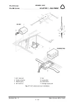
Page 121: ...sert the antenna 4 Fig 7 7 to the hole in the fuselage upper part 7 c Insert the washer 6 screw and tighten the nut 5 to between 25 to 30 inch lbs d Connect the connector 2 to the antenna 4 e Install the circular cover on the aft wall of the baggage compartment f Do an operational test IMPORTANT The AK 451 ELT model produced delivered or fitted after 28 December 2015 is not FAA EASA approved any m...

Page 122: ...M 1 0 00 CHAPTER 7 EQUIPMENT Revision No 11 Date of issue 2014 10 29 7 12 1 ELT main unit 5 Nut 2 Cable connector 6 Lockwasher 3 Mounting tray For information 4 ELT antenna 7 Fuselage upper part Fig 7 7 ELT antenna removal installation ...

Page 123: ... hand c Remove the antiglare shield 2 7 3 11 Antiglare shield installation Type of maintenance line Authorization to perform See point 2 5 3 Tools needed N A a Open the canopy cover 1 Fig 7 8 b Set the antiglare shield 2 to the top of the canopy cover c Screw the thumb screws 3 by hand d During the closing of the canopy cover checking the spaces between the antiglare shield and compass 1 Canopy co...

Page 124: ...r a Open the canopy cover b Loosen the screws 1 Fig 7 9 c Remove the antiglare compass shield 2 7 3 13 Antiglare compass shield installation Type of maintenance line Authorization to perform See point 2 5 3 Tools needed screwdriver a Open the canopy cover b Set the antiglare compass shield 2 Fig 7 9 under the compass c Tighten up the screws 1 1 Screw 2 Antiglare compass shield Fig 7 9 Antiglare co...

Page 125: ...unit For battery replacement refer to Installation and Operation Manual for Model AK 451 Series Doc No IM 451 latest revision IMPORTANT The AK 451 ELT model produced delivered or fitted after 28 December 2015 is not FAA EASA approved any more That ELT model is recommended to be replaced The ELT Kannad 406 AF is an approved replacement ELT KANNAD 406 The transmitter battery expiry date is fixed at ...

Page 126: ...PS 28 Cruiser PS 28N Cruiser CR MM 1 0 00 CHAPTER 7 EQUIPMENT Revision No 25 Date of issue 2021 01 15 7 16 INTENTIONALLY LEFT BLANK ...

Page 127: ...ose wheel fairing 8 10 8 3 7 Removal of nose landing gear wheel 8 11 8 3 8 Installation of nose landing gear wheel 8 12 8 3 9 Removal of the main landing gear leg 8 12 8 3 10 Installation of the main landing gear leg 8 13 8 3 11 Removal of nose landing gear leg 8 14 8 3 12 Installation of nose landing gear leg 8 14 8 3 13 Removal of brake pumps 8 15 8 3 14 Installation of brake pumps 8 15 8 4 Chec...

Page 128: ...5 in Nose wheel WHLNW51CC 75R 5 in Tire and tube Goodyear FLIGHT SPECIAL II 5 00 5 in or equivalent aircraft grade This chapter provides information on main landing gear nose landing gear brake system wheel fairings 8 2 Description and operation 8 2 1 Main landing gear The main landing gear consists of the composite landing gear leg 1 Fig 8 1 wheel axle and wheel 2 equipped with the disc brake 3 T...

Page 129: ...P 8 2 1 1 Main landing gear wheel Main landing gear wheel rim 2 3 Fig 8 2 is pressed of aluminum Wheel rim is split in order to facilitate assembly and disassembly of tire Both halves are joined by bolts 9 Main landing gear wheels are equipped with the brake discs 7 which are attached to the inner half of the wheel rims 3 Wheels are equipped with tires and tubes 6 1 Main landing gear leg 6 Tire wi...

Page 130: ...ounted on the PS 28 Cruiser Original NLG No SG0270N and Improved NLG No SG0300N Improved NLG has enlarged the inner cross section of the tube modified fork used stronger Al alloy and added third reinforcement modified pin used stronger steel Both nose landing gear legs have identical geometry NOTE Due to the similarity of both nose landing gear legs and the same maintenance procedures the original...

Page 131: ...lit in order to facilitate assembly and disassembly of tire Both halves are connected by bolts 9 The wheel is equipped with tire and tube 6 Wheel rims are split in order to facilitate assembly and disassembly of tires 1 Wheel fork 7 Wheel fairing bracket 2 Wheel rim left 8 Wheel fairing 3 Wheel rim right 9 Bolt 4 Wheel axle 10 Spacer 5 Nut and cotter pin 11 Tow bracket 6 Tire with air tube Fig 8 4...

Page 132: ...al depressing 1 Pilot brake pump left 5 Disc brake left 2 Pilot brake pump right 6 Disc brake right 3 Copilot brake pump left 7 Parking brake valve 4 Copilot brake pump right Fig 8 5 Brake system scheme 8 2 3 1 Parking brake The airplane is equipped with the hydraulic manually controlled parking brake The PARKING BRAKE handle is located on the left instrument panel The handle is mechanically conne...

Page 133: ...n the brackets 2 3 b Remove the fairing 1 8 3 2 Installation of main wheel fairing Type of maintenance line Authorization to perform Sport pilot or higher Tools needed Phillips PH2 screwdriver a Set the wheel fairing 1 Fig 8 6 to appropriate position b Attach the fairing 1 with bolts 4 and the washers 5 to the brackets 3 c Attach the fairing 1 with bolts 4 and the washers 5 to the bracket 2 Fig 8 ...

Page 134: ...rake disc and the brake a Jack and support the airplane see 14 2 b Disassemble wheel fairing see 8 3 1 c Remove the lockwire from the bolts 8 Fig 8 7 d Remove the bolts 8 washers 9 and wheel fairing outer bracket 7 e Unscrew three bolts 4 attaching the wheel rim with brake disc 3 f Remove the cotter pin 6 and unscrew the nut 5 g Remove the wheel 1 from the wheel axle 2 Fig 8 7 Main landing gear wh...

Page 135: ...lts threads 4 and attach with it the wheel rim and brake disc 3 d Screw and tighten the nut 5 on the wheel axle 2 e Secure the nut 5 with the new cotter pin 6 f Attach fairing outer bracket 7 with bolts 8 and washers 9 to the axle 2 secure bolts with the lockwire g Install the wheel fairing see 8 3 2 8 3 5 Removal of nose wheel fairing Type of maintenance line Authorization to perform Sport pilot ...

Page 136: ... wheel fairing removal installation 8 3 6 Installation of nose wheel fairing Type of maintenance line Authorization to perform Sport pilot or higher Tools needed Phillips PH2 screwdriver a Set the rear part of the nose wheel fairing 2 Fig 8 8 to appropriate position and attach it with bolts 4 and the washers 7 to the brackets 4 5 b Put the front part of the nose wheel fairing 1 to the rear part of...

Page 137: ... a Jack and support the airplane see 14 2 b Disassemble wheel fairing see 8 3 6 c Remove the cotter pin 6 Fig 8 9 securing nut 4 on wheel axle 2 on one side only d Remove the nut 4 washer and tow bracket 8 from wheel axle 2 e Release the wheel axle 2 from the wheel 1 bushings 3 and the wheel fork eyes 8 Fig 8 9 Nose landing gear wheel removal installation 1 Nose landing gear wheel 2 Wheel axle 3 B...

Page 138: ...w nut 3 set the tow brackets 7 so that the axes of holes for bolts fastening fairings were horizontally tighten nut 3 e Check for free turning of the nose wheel turning must be continual without catching f Secure the nut 3 with the new cotter pin 6 g Install wheel fairing see 8 3 6 8 3 9 Removal of the main landing gear leg Type of maintenance heavy Authorization to perform See point 2 5 3 Tools n...

Page 139: ...maintenance heavy Authorization to perform See point 2 5 3 Tools needed wrench size 9 16 in 1 2 in a Check outer surface of the composite landing gear leg 1 Fig 8 10 for occurrence of cracks and whether the axle connection is not damaged before installing the landing gear leg CAUTION IF THE ORIGINAL SG0030L P MAIN LANGING GEAR LEG 1 IS INSTALLED THE SG0158L P SPACER 10 MUST BE USED IF THE REINFORC...

Page 140: ...horization to perform See point 2 5 3 Tools needed wrench size 1 2 in No 17 a Jack and support the airplane see 14 2 b Remove the lockwire from the bolts 6 Fig 8 11 c Remove the bolts 6 and washers 7 d Remove the tube 5 from the leg bracket 9 e Remove the cotter pin 9 unscrew the nut 3 remove washers 4 bolt 2 and disconnect the shock absorber 8 from the bracket on the nose gear leg 1 f Remove the ...

Page 141: ...ke fluid drain to a previously prepared can from that system line in which you want to remove the brake pump b Disconnect the brake system hose 3 Fig 8 12 from the brake pump 1 2 c Remove cotter pin 7 unscrew nut 11 remove washer 12 spacers 9 10 bolt 8 and disconnect brake pump rod eye from the rudder pedal 14 d Remove cotter pin 7 unscrew nut 5 remove washer 6 bolt 4 and disconnect brake pump fro...

Page 142: ...her 6 secure the nut by the new cotter pin 7 b Connect brake pump rod end eye with pedal 14 by means of the bolt 8 with the nut 11 spacers 9 10 and washer 12 secure the nut by the new cotter pin 7 c Reinstall the brake system hose 3 on the brake pump 1 2 and on the brake cylinder on main landing gear d Fill the brake system with brake fluid and air bleed it see 8 5 4 1 Pilot brake pump 9 Spacer 2 ...

Page 143: ...heck of nose landing gear leg after shimmy occurrence a Remove the nose wheel fairing see 8 3 5 b Remove the nose wheel see 8 3 7 c Remove the cover 7 Fig 8 14 and unload nose landing gear d Check condition of the fork leg and shock absorber for cracks see Fig 8 14 Use magnifying glass e Check tire worn and specified inflation 1 2 0 1 bar 17 4 1 5 psi CAUTION DO NOT EXCESS SPECIFIED TIRE PRESSURE ...

Page 144: ...er 8 Bolt 4 Thrust ring 9 Washer 5 Nut 10 Spring scale Fig 8 14 Check of nose landing gear leg after shimmy occurrence 8 4 3 Check of nose landing gear leg for cracks Tools needed flashlight 10x magnifier a Remove key from ignition switch and disconnect battery b Remove the nose wheel fairing see 8 3 5 c Visually inspect in accordance with FAA AC 43 13 1B Chapter 5 Section 2 Visual Inspection bott...

Page 145: ...e wheel fairing see 8 3 6 2 Connect battery and restore aircraft to the airworthy condition h If an evidence of cracking is badly identified perform the following steps for confirmation not confirmation of cracking 1 Remove nose landing gear leg see 8 3 11 2 Using NDT Penetration Check Kit perform a NDT penetration check in accordance with FAA AC 43 13 1B Chapter 5 Section 5 Penetrant Inspection i...

Page 146: ...PS 28 Cruiser PS 28N Cruiser CR MM 1 0 00 CHAPTER 8 LANDING GEAR Revision No 11 Date of issue 2014 10 29 8 20 Fig 8 15 Inspected area of the nose landing gear leg ...

Page 147: ...lts 1 Fig 8 16 f Set apart both halves of the rim 1 2 and remove the tire 10 with the air tube 11 g Exchange the air tube or the tire if necessary h Put the air tube 11 into the tire 10 and inflate it slightly i Put the inner tube on that half of the rim which has the hole for the valve j Put the other half of the rim on this unit Join both halves of the rim with bolts torque value 11 3 Nm 100 in ...

Page 148: ...plane see 14 2 b Remove the cotter pin 10 Fig 8 17 unscrew the nut 13 remove the washers 12 bolt 11 and disconnect tube 1 from the bracket 2 on the nose gear leg c Remove the cotter pin 10 unscrew the nut 9 and remove the washers 8 6 7 5 d Turn the tube 1 forward and remove tube 1 dumping elements 2 and washers 3 e As needed remove the cotter pins 15 push out the tube 14 and remove profile 18 and ...

Page 149: ...t the lower end of the tube 1 to the bracket 16 install the bolt 11 with the nut 13 and washers 12 secure nut with the new cotter pin 10 j Lower the airplane on jacks 1 Tube 11 Bolt 2 Shock absorber 12 Washer 3 Washer 13 Nut 4 Washer 14 Tube 5 Washer 15 Cotter pin 6 Washer 16 Nose leg bracket 7 Rubber washer 17 Bracket 8 Washer 18 Profile 9 Nut 19 Case 10 Cotter pin Fig 8 17 Change of the dumping ...

Page 150: ... linings 4 by drilling the crimped side of the rivet Do not use punch and hammer Using a 25 drill 0 1495 in diameter drill through rivet taking care to avoid damaging the rivet hole e After drilling crimped edge off rivets lift old lining and remaining rivet pieces from the brake shoe f Inspect the brake shoe 2 3 for any bending or other damage that may have occurred during service A shoe with mor...

Page 151: ...ose landing gear Type of maintenance line Authorization to perform Sport pilot or higher Tools needed wrench size 1 2 in grease gun a Unscrew and remove the bolt 8 Fig 8 14 with the washer 9 and remove cover 7 b By means of the grease gun lubricate axis of rotation CAUTION AVOID TO GREASE CONTAMINATES THE FRICTION AREAS c Apply Loctite 221 on the bolt 8 with the washer 9 and install the cover 7 1 ...

Page 152: ...g hole of the left wheel brake d Unscrew the plug of the left brake cylinder with reservoir using the socket wrench e Slowly fill the brake system with hydraulic fluid f Repeatedly push the brake pedal g Check the brake hose from the point of view of occurrence of bubbles h Continuous occurrence of bubbles indicates a failure of the filling equipment i After the reservoir is filled up to the fille...

Page 153: ...tank removal 9 9 9 3 2 Fuel tank installation 9 10 9 3 3 Removal of the finger screen 9 10 9 3 4 Installation of the finger screen 9 11 9 3 5 Fuel quantity sensor removal 9 11 9 3 6 Fuel quantity sensor installation 9 12 9 3 7 Fuel drain valve removal 9 13 9 3 8 Fuel drain valve installation 9 14 9 4 Check Adjustment 9 14 9 4 1 Checking fuel system tightness 9 14 9 4 2 Fuel pump check 9 14 9 5 Exc...

Page 154: ... and it s delivering to the engine The fuel system of PS 28 Cruiser airplane consists of the following parts two fuel tanks fuel tubing selector valve gascolator mechanical fuel pump located on the engine electrical fuel pump fuel quantity sensor fuel flow meter fuel pressure sensor and drain valves of the fuel tanks Fig 9 1 Fuel system layout page 1 of 5 Instrument panel with EFIS EMS ...

Page 155: ...CR MM 1 0 00 PS 28 Cruiser PS 28N Cruiser CHAPTER 9 FUEL SYSTEM Date of issue 2020 11 19 Revision No 24 9 3 Fig 9 1 Fuel system layout page 2 of 5 Instrument panel with EFIS EMS new design ...

Page 156: ...PS 28 Cruiser PS 28N Cruiser CR MM 1 0 00 CHAPTER 9 FUEL SYSTEM Revision No 3 Date of issue 2012 05 28 9 4 Fig 9 1 Fuel system layout page 3 of 5 Instrument panel with analog instruments ...

Page 157: ...CR MM 1 0 00 PS 28 Cruiser PS 28N Cruiser CHAPTER 9 FUEL SYSTEM Date of issue 2020 11 19 Revision No 24 9 5 Fig 9 1 Fuel system layout page 4 of 5 Instrument panel with analog instruments new design ...

Page 158: ...ft 6 Fuel selector valve 11 Mech fuel pump 16 Fuel quantity indic 2 Fuel tank right 7 Gascolator 12 Carburetor left 17 Fuel pressure indic 3 Filler cap 8 El fuel pump 13 Carburetor right 18 Check valve 4 Fuel quantity sensor 9 Fuel pressure sensor 14 Restrictor jet 5 Finger screen 10 Fuel flow meter 15 EMS Instrument panel with EFIS EMS for certified Rotax 912 ...

Page 159: ...each tank through the filler neck 1 which is located on the top skin close to rib No 6a Fuel drain from the tank is possible through the drain valve 5 located in the rear corner of bottom skin close to the root fuel tank rib 1 Filler neck 4 Finger screen 2 Filler cap 5 Drain valve 3 Venting tube 6 Fuel quantity sensor Fig 9 2 Fuel tank right 9 2 2 Fuel distribution Fuel flows from the tank 1 Fig 9...

Page 160: ...al fuel pump 4 Fuel selector valve Fig 9 3 Fuel system installation diagram 9 2 3 Indication of fuel quantity and pressure Fuel quantity is measured by the fuel float sensor see Fig 9 4 The float position is converted to an electrical signal and fuel quantity in the tank is indicated either on the EMS or on the classical analog instruments see Fig 9 1 Fuel pressure is measured by the electrical fu...

Page 161: ...wrench size No 8 1 2 in screwdriver drill diam 3 2 mm 1 8 in 4 1 mm 5 32 in electric drill cutting pliers pliers a Disconnect the battery b Drain fuel from the fuel system by the tank drain valve c Unscrew the filler cap d Remove the wing see 4 3 1 and put it on the table e Drill out the top half of the leading edge skin f Disconnect wiring from fuel quantity sensor g Disconnect fuel line h Carefu...

Page 162: ...CTITE 565 or equivalent sealant d Close the leading edge skin on the wing and fit it to the spars and ribs per clecos each second hole through of securing harnesses e Rivet the skin on the ribs and spar f Screw back filler cap use silicon to make connection of filler cap flange and wing skin watertight g Install the wing see 4 3 2 h Check the fuel system see 9 4 1 i Connect the battery ground 9 3 ...

Page 163: ...onnect fuel hose 4 on the finger screen tighten the hose clamp 3 c Install the wing see 4 3 2 d Check fuel system tightness see 9 4 1 Fig 9 5 Finger screen removal installation 9 3 5 Fuel quantity sensor removal Type of maintenance line Authorization to perform Sport pilot or higher Tools needed electric drill drill diam 3 2 mm 1 8 in screwdriver cutting pliers pliers a Remove drill off the fuel q...

Page 164: ...quantity sensor 5 Wire 2 Gasket 6 Cover plate 3 Bolt 7 Rivet 4 Washer Fig 9 6 Fuel quantity sensor removal installation 9 3 6 Fuel quantity sensor installation Type of maintenance line Authorization to perform Sport pilot or higher Tools needed Phillips PH2 screwdriver riveting pliers riveter cutting pliers pliers ...

Page 165: ...r see Wiring Manual e Check fuel system tightness see 9 4 1 f Connect the battery and check fuel gauge function g Install rivet the cover plate 6 9 3 7 Fuel drain valve removal Type of maintenance line Authorization to perform Sport pilot or higher Tools needed wrench size 1 2 in NOTE The fuel drain valves are located on bottom side of the wings and on the gascolator a Drain the fuel from the tank...

Page 166: ...ect the pressurization equipment hose to the venting tube outlet on the L R wing bottom side e Disconnect the hoses from the carburetors and return line blind them by plugs f Set the fuel selector valve to LEFT RIGHT position choose the tank g Supply air pressure of 2 kPa 0 02 bar 0 29 psi to the appropriate fuel tank by means of the pressurization equipment h Shut the air pressure supply During 1...

Page 167: ...rplane ground point is located on the nose landing gear leg b Open the fuel tank filler cap c Fill necessary quantity of fuel CAUTION WHEN FILLING FUEL INTO THE AIRPLANE AVOID THE CONTACT OF FUEL WITH THE AIRPLANE SURFACE IT WOULD CAUSE DAMAGE TO SURFACE TREATMENT OF THE AIRPLANE d When the airplane is filled with fuel wipe the filler neck of the rest of fuel and close the fuel neck filler cap e R...

Page 168: ...l to lift the edge of the filter screen 6 and carefully remove it for cleaning f Clean the filter screen 6 by washing in fuel or it can be blown off using an air line inspect bowl 4 and clean if required g Carefully install the filter screen 6 to the gascolator body insert the gasket 5 and the gascolator bowl 4 make sure to correct installation h Tighten the nut 3 and secure it by lockwire i Move ...

Page 169: ...10 12 10 3 Removal Installation 10 13 10 3 1 Removal of the engine from the airplane 10 13 10 3 2 Installation of the engine on the airplane 10 14 10 3 3 Klassic 170 3 R propeller removal 10 16 10 3 4 Klassic 170 3 R propeller installation 10 16 10 3 5 Engine mount removal 10 18 10 3 6 Engine mount installation 10 19 10 3 7 INTENTIONALLY LEFT EMPTY 10 20 10 3 8 INTENTIONALLY LEFT EMPTY 10 20 10 3 ...

Page 170: ...ch propeller 10 34 10 4 Check Adjustment 10 37 10 4 1 Engine test 10 37 10 4 2 Klassic 170 3 R propeller inspections repairs works 10 39 10 4 2 1 Summary of propeller periodical inspection 10 39 10 4 2 2 Prescribed inspection works 10 39 10 4 2 3 Klassic 170 3 R propeller blades pitch setting 10 42 10 4 3 INTENTIONALLY LEFT EMPTY 10 42 10 4 4 3B0R5R68C propeller inspections 10 42 10 4 4 1 Summary ...

Page 171: ...emperature max 130 C 266 F optimum operation 90 110 C 190 230 F Oil pressure max 7 bar 102 psi min 0 8 bar 12 psi optimum operation 2 5 bar 29 73 psi Fuel pressure max 0 4 bar 5 8 psi min 0 15 bar 2 2 psi With the change to a new cylinder heads design for the ROTAX 912 ULS2 engines from S N 6 781 410 inclusive and for 912 S2 engines from S N 4 924 544 inclusive or on all engines with type designat...

Page 172: ...EW CYLINDER HEAD DESIGN Type of coolant used by the aircraft manufacturer is shown in the Section 17 5 Fuel type MOGAS EN228 Super or EN 228 Super plus with max 5 ethanol blend min RON 95 ASTM D4814 min AKI 91 AVGAS 100LL ASTM D910 ASTM D7547 refer to the Rotax Operator s Manual Section 2 4 Operating media Fuel Rotax Service Instructions SI 912 016 Oil type refer to the Rotax Operator s Manual Sec...

Page 173: ...t of the lower cowling 2 there is a hole for air inlet to the oil cooler On the left side in the lower cowling 2 there is a hole 6 for air inlet to the air filter to the engine inlet system 1 Upper engine cowling 5 Access cover 2 Lower engine cowling 6 Air inlet hole for engine inlet system 3 Air inlet hole for radiator 7 Landing light 4 Quick fasteners 8 Air inlet hole for cylinder cooling Fig 10...

Page 174: ... is combined cylinder heads are liquid cooled and cylinders are air cooled Cooling circuit of cylinder heads is made as a closed system containing the pump 5 Fig 10 3a expansion tank 4 with the pressure cap 3 cooler 2 thermostatic valve 6 and the overflow bottle 1 1 Overflow bottle 4 Expansion tank 2 Cooler 5 Pump 3 Pressure cap 6 One circuit thermostatic valve Fig 10 3a Cooling system with one ci...

Page 175: ... Expansion tank 2 Cooler 5 Pump 3 Pressure cap 6 Dual circuit thermostatic valve Fig 10 3b Cooling system with dual circuit thermostatic valve 1 Overflow bottle 4 Expansion tank 2 Cooler 5 Pump 3 Pressure cap 6 Dual circuit thermostatic valve Fig 10 3c Cooling system with dual circuit thermostatic valve mount on pump 1 2 3 4 5 6 ...

Page 176: ...l through the thermostatic valve 9 and the oil cooler 5 to the lubricated points on the engine The oil pump is equipped with the pressure relief valve 1 and with the oil pressure sensor 2 The oil tank is ventilated by venting 7 which is connected to hose and is led under the airplane Oil pressure and temperature are indicated either on the EMS or on the classical analog instruments 1 Pressure reli...

Page 177: ...ssue 2021 01 15 Revision No 25 10 9 1 Pressure relief valve 6 Oil filter 2 Oil pressure sensor 7 Oil tank venting 3 Oil pump 8 Oil temperature sensor 4 Oil tank 9 Thermostatic valve 5 Oil cooler Fig 10 4b Oil cooling system thermostatic valve mount on pump 4 5 2 6 7 3 9 1 8 ...

Page 178: ... Heat exchanger 6 Water cooler 3 Exhaust 7 CABIN HEATING knob 4 Air filter 8 CARB HEAT knob Fig 10 5 Air inlet system 10 2 1 8 Exhaust system Exhaust system of PS 28 Cruiser SportCruiser airplane consist of four exhaust tubes 1 Fig 10 6 which lead exhaust gases from individual cylinders to the muffler 2 The muffler serves at the same time as a silencer Exhaust gases are led from there by the exhau...

Page 179: ...he spark plugs by means of high voltage cables The sequence of individual cylinder ignition of the engine is as follows 1 4 2 3 Ignition circuits are controlled by the keyed ignition switch on the instrument panel Positions of ignition switch OFF Engine ignition of R Only ignition circuit A on spar plugs 1 2 top 3 4 bottom L Only ignition circuit B on spar plugs 3 4 top 1 2 bottom BOTH Both circui...

Page 180: ... co cured bonded stainless steel Sensenich The propeller surface is provided with a sprayed on coat of resistant polyurethane varnish The composite propeller spinner is a part of the propeller The propeller is attached to the engine by means of bolts Technical data of the propellers Woodcomp propellers Propeller manufacturer Woodcomp s r o Propeller type Klassic 170 3 R Max speed 2 600 rpm Diamete...

Page 181: ...firewall e Shut the fuel selector valve possibly drain fuel from the fuel installation f Drain oil from the engine see 10 5 1 and cooling liquid see 10 5 2 g Disconnect hoses of the oil and the cooling system h Remove the oil cooler see 10 3 13 and the water cooler see 10 3 15 i Disconnect control of carburetors and carburetors heating j Remove air intake see 10 3 9 k Remove the exhaust system see...

Page 182: ...intenance heavy Authorization to perform See point 2 5 3 Tools needed wrench size No 8 No 9 3 8 7 16 9 16 Allen wrench size No 4 screwdriver cutting pliers pliers Cobra pliers for clamps a Put the engine 1 Fig 10 8 on the engine mount 4 by the crane or with 2 assistants and attach it by the bolts 2 with washers 3 Tighten up to a torque of 40 Nm 354 inch lb b Secure the bolt heads 2 by lockwire see...

Page 183: ...0 8 connect control cables of the throttle and the choke on the carburetors control levers Adjust throttle control see 10 4 5 and the choke see 10 4 6 1 Carburetor left 4 Choke control cable 2 Airbox 5 Throttle control lever 3 Throttle control cable 6 Choke control lever Fig 10 9 Throttle and choke control connection l Connect the air hose from the heat exchanger for heating the airplane cockpit m...

Page 184: ...rs 12 and remove the propeller spinner 2 c Cut of the lockwire securing the bolt heads 7 d Unscrew and remove the bolts 7 with the washers 10 and take out the propeller along with spinner flange 9 from the spacer 3 e Put the protective covers on the propeller blades and store the propeller on a safe place so that no damage can occur Fig 10 10 Klassic 170 3 R propeller removal installation 10 3 4 K...

Page 185: ...ut visual check of the propeller integrity and condition d Check out possibly adjust the blades pitch of propeller according to the propeller manual NOTE Propeller pitch is factory set to 17 5 0 5 e Attach the propeller 1 and the propeller flange 9 to the spacer 3 on the engine flange 6 by means of the bolts 7 with washers 10 f Secure the airplane against its movement see 14 5 g Tighten the bolts ...

Page 186: ...en up with torque 20 Nm 15 ft lb connect the battery 10 3 5 Engine mount removal Type of maintenance heavy Authorization to perform See point 2 5 3 Tools needed wrench size 9 16 screwdriver torque wrench cutting pliers pliers WARNING ENGINE IGNITION MUST BE SWITCHED OFF a Remove engine cowlings b Disconnect the battery and remove upper line of spark plugs from the engine c Remove the engine and al...

Page 187: ...GNITION MUST BE SWITCHED OFF a Install the engine mount 1 Fig 10 13 and screw self lock nuts 2 Tighten up to a torque of 20 Nm 177 inch lb b Install the engine and all other parts see CR MM 1 0 00 chapter 10 3 2 the latest revision c Mount all cables by the cable tie d Connect the battery and install upper line of spark plugs to the engine e Install the engine cowlings f Restore the aircraft to th...

Page 188: ...PS 28 Cruiser PS 28N Cruiser CR MM 1 0 00 CHAPTER 10 POWERPLANT Revision No 24 Date of issue 2020 11 19 10 20 10 3 7 INTENTIONALLY LEFT EMPTY 10 3 8 INTENTIONALLY LEFT EMPTY ...

Page 189: ...screw the screws 10 Fig 10 14 with the washers 11 and remove the propeller spinner 2 c Unscrew and remove the nuts 6 the washers 7 and take out the propeller 1 along with the spinner flange 9 and spacer 3 from the propeller flange 12 d Put the protective covers on the propeller blades and store the propeller on a safe place so that no damage can occur Fig 10 14 3B0R5R68C propeller removal installa...

Page 190: ... bolts through the assembled propeller hub NOTE Each washer 7 works in pairs with the ramped sides facing each other No other washers may be used in combination with those washers g Insert bushings 4 into the engine flange 12 from the back side protruding into the spacer h Place spinner flange 9 spacer 3 and the assembled propeller 1 on the propeller mounting flange 12 The hub must sit flush on th...

Page 191: ...ut the propeller spinner 2 Fig 10 14 on the propeller and attach it with screws 10 and washers 11 10 3 11 Air intake system removal Type of maintenance line Authorization to perform Sport pilot or higher Tools needed wrench size No 8 No 10 screwdriver WARNING ENGINE IGNITION MUST BE SWITCHED OFF a Remove the upper engine cowling b Disconnect the control cable 13 Fig 10 17 from the air intake chang...

Page 192: ...e 11 Washer 4 Hose clamp 12 Nut 5 Cable tie 13 Control cable 6 Drain hose 14 Air intake changeover lever 7 Drain hose 15 Air hose preheated air 8 Air hose cold air 16 Hose clamp Fig 10 15 Air intake system removal installation 10 3 12 Air intake system installation Type of maintenance line Authorization to perform Sport pilot or higher Tools needed wrench size No 8 No 10 screwdriver ...

Page 193: ...ad them on the engine mount in direction down the airplane and secure them by hose fasteners 5 16 fix them by cable ties on the engine mount e Connect the carburetors control cable of 13 to the lever 14 adjust function of carburetors heating knob f Install the upper engine cowling 10 3 13 Exhaust system removal Type of maintenance line Authorization to perform See point 2 5 3 Tools needed wrench s...

Page 194: ...ut 3 Exhaust tube 2 8 Heat exchanger 4 Exhaust tube 3 9 Spring 5 Exhaust tube 4 Fig 10 16 Exhaust system removal installation 10 3 14 Exhaust system installation Type of maintenance line Authorization to perform See point 2 5 3 Tools needed wrench size No 13 pliers small wire hook spring removal assembly jig WARNING ENGINE IGNITION MUST BE SWITCHED OFF ...

Page 195: ... installed parts e Put on muffler 1 heat exchanger 8 and secure it by means of springs 9 f Install air hoses on the heat exchanger see 10 3 12 g Install engine cowlings 10 3 15 Oil cooler removal Type of maintenance line Authorization to perform Sport pilot or higher Tools needed wrench size No 19 No 30 WARNING ENGINE IGNITION MUST BE SWITCHED OFF a Remove the upper and lower engine cowling b Drai...

Page 196: ...e cooler necks install the upper pairs of washers 2 3 and gradually tight the nuts 4 b Install the banjo fittings 5 screw the banjo bolts 6 with sealing rings 7 and secure these bolts with the lockwire see 15 8 2 c Install hoses 8 on the banjo fittings 5 and secure them with hose clamps 9 d Fill the oil system with oil see 10 5 1 and check oil system tightness e Install the lower and upper engine ...

Page 197: ...r Tools needed wrench size No 10 No 17 screwdriver WARNING ENGINE IGNITION MUST BE SWITCHED OFF a Remove the upper and lower engine cowling b Drain the cooling liquid from the cooling system see 10 5 2 c Remove the hose clamps 9 Fig 10 15 and disconnect hoses 10 12 from the cooler outlets d Loose the bolts 7 e Remove four nuts 5 washers 6 and cooler 1 f As necessary remove the silentblocks 4 from ...

Page 198: ...her 2 Lower bracket 9 Hose clamp 3 Upper bracket 10 Hose 4 Silentblock 11 Tube 5 Cap nut 12 Hose 6 Lock washer 13 Tube 7 Bolt Fig 10 18 Water cooler removal installation 10 3 18 Water cooler installation Type of maintenance line Authorization to perform Sport pilot or higher Tools needed wrench size No 10 No 17 screwdriver ...

Page 199: ...d see 10 5 2 and check system tightness f Install the lower and upper engine cowling 10 3 19 Throttle and choke control levers removal Type of maintenance line Authorization to perform See point 2 5 3 Tools needed wrench size No 14 Allen wrench size No 2 screwdriver cutting pliers WARNING ENGINE IGNITION MUST BE SWITCHED OFF a Remove the cover 11 Fig 10 19 from the middle channel b Remove the uppe...

Page 200: ... Choke cable 3 Bushing 10 Choke bowden 4 Bushing For information 5 Nut 11 Cover 6 Washer 12 Choke lever 7 Throttle cable 13 Throttle lever Fig 10 19 Throttle control lever 10 3 20 Throttle and choke control levers installation Type of maintenance line Authorization to perform See point 2 5 3 Tools needed wrench size No 14 Allen wrench size No 2 Screwdriver cutting pliers ...

Page 201: ... with choke 1 and to the carburetor levers 12 13 f Install the cover 11 on the middle channel g Install the upper engine cowling h Check for continuous travel of the throttle and choke control lever i Adjust the throttle and choke control see 10 4 5 10 4 6 10 3 21 Carburetors heating knob removal Type of maintenance line Authorization to perform Sport pilot or higher Tools needed wrench size No 8 ...

Page 202: ... 19 on the changeover lever 14 of the air intake d Adjust carburetors heating control see 10 4 4 10 3 23 V belt pulley removal Klassic propeller Type of maintenance line Authorization to perform See point 2 5 3 Tools needed wrench size No 13 No 16 5 8 Allen wrench size No 6 screwdriver cutting pliers pliers WARNING ENGINE IGNITION MUST BE SWITCHED OFF a Remove the Klassic propeller see 10 3 3 b Un...

Page 203: ... V belt pulley removal installation Klassic propeller 10 3 25 V belt pulley removal Sensenich propeller Type of maintenance line Authorization to perform See point 2 5 3 Tools needed wrench size No 13 No 16 5 8 Allen wrench size No 6 screwdriver cutting pliers pliers WARNING ENGINE IGNITION MUST BE SWITCHED OFF a Remove the Sensenich propeller see 10 3 9 b Unscrew the screw 12 Fig 10 20c around th...

Page 204: ...perform See point 2 5 3 Tools needed wrench size No 13 No 16 5 8 Allen wrench size No 6 screwdriver cutting pliers pliers WARNING ENGINE IGNITION MUST BE SWITCHED OFF a Set on the V belt pulley 2 Fig 10 20c b Screw the screws 3 to the V belt pulley c Install the Sensenich propeller see 10 3 10 Fig 10 20c V belt pulley removal installation Sensenich propeller 1 Propeller 2 V belt pulley 3 Screw 8 p...

Page 205: ...onitor oil pressure NOTE If oil pressure do not rise within 10 sec above min pressure 0 8 bar 12 psi switch off the engine Is admissible max oil pressure 7 bar 102 psi for a short period at cold start Fuel pressure has been in range from 0 15 to 0 4 bar 2 2 to 5 8 psi f Engine warm up according to the POH Section 4 2 3 and the Rotax Operator s Manual Section 3 As soon as oil pressure will be in ra...

Page 206: ...ing cold start for a short term only RPM drop between ignition position BOTH and position L or R must not exceed 300 rpm Mutual difference between left L and right R ignition circuit must not exceed 115 rpm Max ground engine speed and idle varies according to the type of propeller Klassic 170 3 R max 5 000 100 rpm idle 1 650 50 rpm 3B0RTR68C max 4 950 100 rpm idle 1 650 50 rpm With the change to a...

Page 207: ...ation or months whichever comes first NOTE Inspection overhaul of propeller must also be performed in the following cases The propeller has contacted the ground and or foreign object The propeller has been overspeed see max operating RPM in User s Manual The propeller has been damaged The propeller has no record of operating hours and or calendar months 10 4 2 2 Prescribed inspection works NOTE In...

Page 208: ... deformation As a damage it is not mentioned the usual operational wear by friction operation washing etc Relevant findings of failures must not be of a higher extent than stated in the Operator s manual UM 07 see the latest issue on the Woodcomp websites The small failures stated in the Operators manual can be repaired by the Certifying staff EU1321 2014 see 2 5 1 for details h If the inspection ...

Page 209: ...ce with polyurethan email Repair of hub and metal propeller parts Repairs of hub and metal propeller parts are strictly prohibited Repair of spinner and spinner plate Only repairs relating to small surface grooves on the outside spinner part or spinner plate with max depth of 0 5 mm are allowed Repairs of damaged or corrosion affected rivet nuts on the spinner plate are not allowed Instructions fo...

Page 210: ... described in the propeller manufacturer documentation Sensenich Three Blade Composite Aircraft Propeller Installation and Operation Instructions for Rotax Engines Instructions for Continued Airworthiness 10 4 5 Adjusting throttle control a Pull the throttle control to the stop The throttle lever on the carburetor 5 Fig 10 9 must be on the stop The bowden must be supported in the terminals b Relea...

Page 211: ...h lock wire Mark all bolted joints with red paint 10 4 8 Checking exhaust system WARNING CHECK OF EXHAUST SYSTEM VERY CAREFULLY THE BURST OR LEAKY EXHAUST CAN EXPOSE THE CREW TO DANGER PRESENTED BY CARBON MONOXIDE OR CAN RESULT IN ENGINE POWER LOSS POSSIBLY FIRE Check the exhaust system for cracks Pay special attention to the following areas muffler in the area of the input and the output pipe and...

Page 212: ...not drop below min mark Fig 10 22 Oil volume check Oil draining Drain oil from the oil tank by unscrewing the plug wrench size No 17 on the lower side of the oil tank It is possible to drain oil from the engine after unscrewing the plug in the lower part of the engine at the hose of the return branch of oil flow It is recommended to drain oil immediately after engine test or after finishing the op...

Page 213: ...iquid into the expansion tank in the engine compartment In addition to this there is a overflow bottle which collects cooling liquid in case of engine overheating and is attached to the fire wall 10 5 3 Exchange Check of oil filter Refer to the Rotax Maintenance Manual Chapter 12 00 00 Section 5 Oil System NOTE Carry out at every oil exchange WARNING RISK OF SCALDS AND BURNS Always allow the engin...

Page 214: ...ten by hand after the engine test on a cold engine 10 5 4 Exchange Check of air filter a Remove the hose fastener and the bracket attaching the air filter to the left side lower engine cowling and remove the air filter b Inspect the air filter and if contaminated clean it according to instructions in the Rotax Maintenance Manual Chapter 12 00 00 Section 2 4 c Attach the cleaned or the new filter t...

Page 215: ...1 11 11 3 1 Electrical safety 11 11 11 3 2 Battery removal 11 11 11 3 3 Battery installation 11 11 11 3 4 Position strobe light removal 11 12 11 3 5 Position strobe light installation 11 13 11 3 6 D112 SX landing light removal engine cowling 11 14 11 3 7 D112 SX landing light installation engine cowling 11 15 11 3 8 Taxi Landing light removal winglet 11 15 11 3 9 Taxi Landing light installation wi...

Page 216: ...tributed to the individual systems by means of the main busbar Systems are protected by circuit breakers which are permanently ON and switches circuit breakers which are turning ON as needed If some of the circuit is overloaded then the circuit breaker disconnects the circuit Some circuits are protected by the fuses After switching the MASTER BAT switch ON and by turning the ignition key to the po...

Page 217: ...CR MM 1 0 00 PS 28 Cruiser PS 28N Cruiser CHAPTER 11 ELECTRICAL SYSTEM Date of issue 2011 03 08 Revision No 11 3 Fig 11 1 Electrical system scheme ...

Page 218: ... EFIS NAV COM GPS XPDR FUEL P Switch of electric fuel pump NAV L Switch of position lights STROBE Switch of strobe lights LDG L Switch of landing light COCKPIT L Rotary switch of cockpit lamp with dimmer INSTR L Rotary switch of instrument lighting with dimmer FLAPS UP DOWN Switch of flaps control Switches instrument panel with the analog instruments Designation Description MASTER BAT Main switch ...

Page 219: ...generator MASTER GEN 2 Main switch switch of additional generator MFD 1 Switch of Multi Function Display 1 MFD 2 Switch of Multi Function Display 2 AVIONICS Switch of EFIS NAV COM GPS XPDR FUEL P Switch of electric fuel pump NAV L Switch of position lights STROBE Switch of strobe lights LDG L Switch of landing light TAXI L Switch of taxi light RECOG L Switch of recognisation light PITOT HEAT Switc...

Page 220: ...ENG INSTR 1A Circuit breaker of engine instruments NAV 2A Circuit breaker of optional navigation device GPS 3A Circuit breaker of GPS XPDR 5A Circuit breaker of transponder ATT 2A Circuit breaker of attitude indicator DG 4A Circuit breaker of directional gyro TURN IND 1A Circuit breaker of turn bank indicator FUEL P 3A Circuit breaker of electric fuel pump FLAPS 3A Circuit breaker of flaps TRIM 2A...

Page 221: ...Circuit breaker of electric fuel pump NAV L 5A Circuit breaker of position lights STROBE 10A Circuit breaker of strobe lights LDG L 3A Circuit breaker of landing light TAXI L 3A Circuit breaker of taxi light RECOG L 5A Circuit breaker of recognition light PITOT HEAT 5A Circuit breaker of pitot heating COMM 10A Circuit breaker of VHF transceiver IC 1A Circuit breaker of intercom NAV 4A Circuit brea...

Page 222: ... ENGIN INSTR Fuse of engine instruments 25A DC GEN Fuse of generator 25 A BATTERY Fuse of battery Fuses instrument panel with the Skyview 1A SIGN DOOR Fuse of unlocked canopy signaling system 25A DC GEN Fuse of generator 25 A BATTERY Fuse of battery Fuses instrument panel with Dynon Skyview and Garmin G5 1A VOLTMETER Fuse of voltmeter Tab 11 3 Fuses 11 2 4 Generator The generator is a part of the ...

Page 223: ...ance free battery is installed on firewall Battery can be charged directly in the airplane after its disconnecting from the onboard electrical system Technical parameters Voltage 12 V Nominal capacity 20 Ah Max discharge current 300 A 5 s Short circuit current 1 000 A Range of operation temperatures 20 to 60 C 4 to 140 F Service life is about 3 5 years or at capacity drop below 80 Weight 6 kg 13 l...

Page 224: ...he airspeed indicator is switched controlled by the switch INSTR L The cockpit lamp is switched controlled by the switch COCKPIT L External lighting for VFR Night aircraft consists of LED position strobe which are located in the wing tips at the bottom of the fuselage and at the end of the rudder These lights are switched by the switch STROBE and NAV L In the right winglet is also located a taxi l...

Page 225: ...Battery removal Type of maintenance line Authorization to perform Sports pilot or higher Tools needed screwdriver wrench size No 8 a Set the MASTER BAT MASTER GEN switches to OFF b Remove engine cowlings c Unscrew the bolts 5 Fig 11 3 with washers 6 and disconnect the wires 2 3 4 from the battery contacts make sure to disconnect the negative lead first d Unscrew the bolts 8 with washers 9 disconne...

Page 226: ... Wire 9 Washer 5 Bolt 10 Firewall Fig 11 3 Battery removal installation 11 3 4 Position strobe light removal Type of maintenance line Authorization to perform Sports pilot or higher Tools needed screwdriver a Set the MASTER BAT NAV L and STROBE switches to OFF b Unscrew the screw 4 Fig 11 4 and carefully release the light 1 c Disconnect the wires 3 and remove position strobe light 1 with the gaske...

Page 227: ...11 4 through the appropriate hole in the gasket 2 b Connect the position strobe light wires 3 see Wiring Manual c Set the position light 1 with the gasket 2 to the wing tip 5 and fasten it with screw 4 d Set the MASTER BAT NAV L and STROBE switches to ON and check the correct function of position strobe lights e Set the MASTER BAT NAV L and STROBE switches to OFF 1 Position light 4 Screw 2 Gasket ...

Page 228: ...ex wrench No 4 wrench No 8 a Set the MASTER BAT and LDG L switches to OFF b Remove the engine cowlings c Disconnect the connector on the cable 2 Fig 11 5 d Unlock the lockwasher 6 e Unscrew and remove the nut 4 washers 5 6 screw 3 and landing light 1 and carefully release the light 1 1 D112 SX landing light 5 Washer 2 Cables with connector 6 Lockwasher 3 Screw For information 4 Nut 7 Threaded eye ...

Page 229: ... BAT and LDG L switches to ON and check the correct function of landing light as necessary adjust the landing light d Set the MASTER BAT and LDG L switches to OFF e Tighten the nut 4 and secure it with washer 6 f Install the engine cowlings 11 3 8 Taxi Landing light removal winglet Type of maintenance line Authorization to perform See point 2 5 3 Tools needed torx wrench hex wrench wrench Philips ...

Page 230: ...e line Authorization to perform See point 2 5 3 Tools needed torx wrench hex wrench wrench Philips screwdriver a Install the light 1 Fig 11 6 to the holder and screw it by the screws 8 with washers 9 b Push the cable 10 through metal cover 5 and connect the connector c Attach metal cover 5 to the winglet with screws 6 and washers 7 d Install cover 3 with sealing 4 and screw the screws 2 e Set the ...

Page 231: ...r 3 and sealing 4 c Gently loosen the screws 5 d Install the laser perpendicular to the light plane 1 WARNING WEAR LASER PROTECTIVE GLASSES e Turn on the laser f Adjust the light so that the laser beam is directed into the circle on the wall See Fig 11 8 g Tighten the screws 5 h Turn of the laser i Remove the laser from the light j Install cover 3 with sealing 4 and screw the screws 2 1 Taxi Landi...

Page 232: ...0 00 CHAPTER 11 ELECTRICAL SYSTEM Revision No 25 Date of issue 2021 01 15 11 18 Fig 11 8 Taxi Landing light adjustment 3000 mm 118 1 665 mm 26 2 wall airplane axis 90 laser beam laser beam 250 mm 9 8 3320 mm 130 7 775 mm 30 5 3510 mm 138 2 ...

Page 233: ...the battery from the onboard electrical network b Clean the battery contacts and connect the charging device on them Mind the polarity c Charging voltage at temperature of 25 C 77 F is Cycle use 14 5 14 9 V Standby use 13 6 to 13 8 V Maximum charging current is 8 A d After charging grease the battery contacts with lubricating grease and reconnect the battery to the onboard electrical network ...

Page 234: ...PS 28 Cruiser PS 28N Cruiser CR MM 1 0 00 CHAPTER 11 ELECTRICAL SYSTEM Revision No 20 Date of issue 2017 12 05 11 20 Fig 11 9 Battery characteristics ...

Page 235: ...tector 12 26 12 3 7 Removal of the flight instruments 12 27 12 3 8 Installation of the flight instruments 12 28 12 3 9 Removal of the EFIS D100 12 29 12 3 10 Installation of the EFIS D100 12 31 12 3 11 Removal of EDC 10A remote compass module 12 31 12 3 12 Installation of EDC 10A remote compass module 12 32 12 3 13 Removal of the EMS D120 12 32 12 3 14 Installation of the EMS D120 12 34 12 3 15 Re...

Page 236: ... 46 Removal of TC20 transponder control unit 12 54 12 3 47 Installation of TC20 transponder control unit 12 55 12 3 48 Removal of SV HDX1100 display 12 55 12 3 49 Installation of SV HDX1100 display 12 57 12 4 Check Adjustment 12 58 12 4 1 Check of pitot static system tightness 12 58 12 4 2 Dynon avionics pitot static test 12 58 12 4 3 Magnetic compass compensation 12 59 12 4 4 EFIS compass heading...

Page 237: ...695 24 PARKING BRAKE knob 6 EMS D120 25 CARBURETOR HOT AIR knob 7 COCKPIT L dimmer 26 CABIN HEATER knob 8 INSTR L dimmer 27 BRS activation handle 9 Lighting cover 28 PM3000 intercom 10 Air vent 29 VOLUME Dynon alerts control 11 MASTER BAT switch 30 Circuit breakers 12 MASTER GEN switch 31 ELT remote switch 13 EMS switch 32 Cockpit light 14 AVIONICS switch 33 Magnetic compass 15 FUEL P switch 34 HS...

Page 238: ... Lighting cover 27 PM3000 intercom 10 Air vent 28 VOLUME Dynon alerts control 11 MASTER BAT switch 29 Circuit breakers 12 MASTER GEN switch 30 ELT remote switch 13 EMS switch 31 Cockpit light 14 AVIONICS switch 32 Magnetic compass 15 FUEL P switch 33 HS34 HSI expansion module 16 NAV L switch 34 EMS ALARM yellow warning light 17 STROBE switch 35 CABIN OPENED red warning light 18 LDG L switch 36 BRS...

Page 239: ...ure indicator 36 Elevator TRIM UP DOWN 12 Fuel quantity indicator 37 AILERON TRIM L R 13 Oil temperature indicator 38 Circuit breakers 14 CHT CT indicator 39 Hourmeter 15 Voltmeter 40 ELT remote switch 16 SL40 VHF transceiver 41 Cockpit light 17 Air vent 42 Magnetic compass 18 Lighting cover 43 NIGHT POS IND DAY switch 19 MASTER BAT switch 44 DIM instrument lighting dimmer 20 MASTER GEN switch 45 ...

Page 240: ... Socket 12V 29 Keyed ignition switch 10 Air vent 30 STALL WARNING TEST button 11 MASTER BAT switch 31 STALL WARNING light 12 MASTER GEN 1 switch 32 EMS ALARM warning light 13 MASTER GEN 2 switch 33 CABIN OPENED warning light 14 MFD 1 switch 34 PITOT HEAT light 15 MFD 2 switch 35 PARKING BRAKE knob 16 AVIONICS switch 36 CARBURETOR HOT AIR knob 17 FUEL P switch 37 CABIN HEAT knob 18 NAV L switch 38 ...

Page 241: ...CR MM 1 0 00 PS 28 Cruiser PS 28N Cruiser CHAPTER 12 INSTRUMENTS AND AVIONICS Date of issue 2015 09 07 Revision No 14 12 7 INTENTIONALLY LEFT BLANK ...

Page 242: ...TER GEN switch 27 BRS activation handle option 11 EFIS 1 circuit breaker 28 INSTR L dimmer option 12 EFIS 2 circuit breaker 29 Circuit breakers 13 AVIONICS switch 30 RH D1000 USB port 14 FUEL P circuit breaker 31 ELT remote switch 15 NAV L circuit breaker 32 Socket 12 V 16 STROBE circuit breaker 33 Transponder control unit 17 LDG L circuit breaker 34 EMS ALARM yellow warning light NOTE In case the...

Page 243: ...ed to the ASI and EFIS Airplanes equipped with Skyview Static and total pressure is lead to the ADAHRS ALT ASI and transponder The drain sumps are installed on the both flexible hoses Airplanes equipped with Skyview and Garmin G5 Static and total pressure is lead to the ADAHRS Garmin G5 and transponder The drain sumps are installed on the both flexible hoses Fig 12 6 Location of the pitot heat lig...

Page 244: ...evision No 4 Date of issue 2012 12 10 12 10 The proper function of the system can be checked by pressing STALL WARNING TEST button 2 located on the left instrument panel Fig 12 7 Location of the stall warning light and test button 1 STALL WARNING light 2 STALL WARNING TEST button ...

Page 245: ...CR MM 1 0 00 PS 28 Cruiser PS 28N Cruiser CHAPTER 12 INSTRUMENTS AND AVIONICS Date of issue 2014 10 29 Revision No 11 12 11 Fig 12 8 Pitot static system scheme page 1 of 2 ...

Page 246: ...r CR MM 1 0 00 CHAPTER 12 INSTRUMENTS AND AVIONICS Revision No 25 Date of issue 2021 01 15 12 12 Fig 12 8 Pitot static system scheme page 2 of 2 Airplanes equipped with Dynon SkyView system and Garmin G5 ADAHRS XPDR C U GARMIN G5 ...

Page 247: ... up to 20 000 ft Magnetic compass The magnetic compass is designed to determine magnetic course of the airplane The magnetic compass is positioned on the upper edge of the instrument panel and consists of the vessel filed with nonfreezing liquid with the little window in the front wall The compass rose is positioned on the rotary and swinging pivot inside the compass EFIS D100 The Dynon D100 is a ...

Page 248: ...400 1 400 5 500 5 500 5 800 5 800 Oil Pressure 0 8 bar 0 8 2 bar 2 5 bar 5 7 bar 7 bar Oil Temperature 50 C 50 90 C 90 110 C 110 130 C 130 C Cylinder head Temperature CHT to 50 C 50 135 C 135 C Coolant Temperature CT 50 120 C 120 C Exhaust Gas Temp to 300 C 300 850 C 850 880 C 880 C Fuel Pressure 0 15 bar 0 15 0 4 bar 0 15 0 5 bar 0 4 bar 0 5 bar 0 14 bar 0 14 0 15 bar 0 15 0 50 bar 0 50 0 51 bar ...

Page 249: ... refer to SL 40 Installation Manual P N 560 0956 02a latest edition and Pilot s Guide P N 560 0954 02 latest edition Fig 12 11 SL 40 VHF transceiver The Garmin GTR 225 is a 760 channel 25 kHz spacing or 2280 channel 8 33 kHz spacing VHF Comm transceiver NOTE For detailed information refer to Garmin GTR 225 Installation Manual P N 190 01182 02 latest edition and Pilot s Guide P N 190 01182 10 lates...

Page 250: ...configuration selection The unit also features an altitude monitor and flight timers A voice or tone audio output announces altitude deviation and count down timer expiration NOTE For detailed information refer to GTX 328 Maintenance Manual P N 190 00420 05 latest edition and Pilot s Guide P N 190 00420 03 latest edition Fig 12 15 GTX 328 transponder The panel mounted GTX 330 is a TSO certified Mo...

Page 251: ...agonal high definition sunlight readable color display NOTE For detailed information refer to GPS 695 696 Owner s Manual P N 190 00919 00 latest edition Fig 12 17 GPSMAP 695 696 The Aera 510 presents GPS derived analog flight instrumentation position navigation and hazard avoidance information to the pilot using a bright 4 3 inch diagonal high definition sunlight readable color display with touch ...

Page 252: ...uchscreen The GTN 750 is a GPS SBAS unit that meets requirements TSO C146c and may be approved for IFR end route terminal oceanic non precision and precision approach operations The GTN 650 unit includes an airborne VHF communications transceiver and airborne VOR LOC and G S receivers NOTE For detailed information refer to GTN 6XX 7XX AML STC Installation Manual P N 190 01007 A3 latest edition and...

Page 253: ...a rich and intuitive user interface The GTN 750 is a GPS SBAS unit that meets requirements TSO C146c and may be approved for IFR en route terminal oceanic non precision and precision approach operations The GTN 750 unit includes an airborne VHF communications transceiver and airborne VOR LOC and G S receivers NOTE For detailed information refer to GTN 6XX 7XX AML STC Installation Manual P N 190 01...

Page 254: ...Garmin G5 unit is 3 125 in wide and 3 125 in tall It features a 3 5 in color LCD display The unit delivers as a standalone primary source for aircraft attitude information It also displays secondary information such as airspeed and altitude NOTE For detailed information refer to G5 Installation Manual P N 190 01112 10 latest edition and Pilot s Guide P N 190 01112 12 latest edition Fig 12 21 Garmi...

Page 255: ...xt generation of glass panel avionics for light sport aircraft The system architecture is shown on Fig 12 23 The SV D1000 and SV HDX1100 displays are very bright high resolution screens and contain the main control CPU graphics processor and terrain data base Displays can act as a Primary Flight Display PFD with Synthetic Vision an Engine Monitoring System EMS and a Moving Map in a variety of cust...

Page 256: ...EMS based attitude reference and air data computer integrated with a digital compass This allows easier mounting and higher accuracy calibration between the system components Coolant temperature in case the engine is equipped with new cylinder heads P N 413185 for 2 3 cylinder head The GPS position is provided by the SV GPS 250 module Convenient program and data updates via USB memory stick NOTE F...

Page 257: ...s cutting pliers a Loose securing bolt 4 Fig 12 24 in the pitot static tube bracket 2 and pull out a bit the pitot static tube 1 with hoses from the bracket b Remove the cable ties from hoses 3 The hose and tube for static pressure line mark by S letter and for total pressure mark by T letter c Disconnect the transparent hoses 3 of static and total pressure from the ports on the pitot static tube ...

Page 258: ...RT MARKED BY T LETTER b Insert the pitot static tube 1 in the bracket 2 c Secure pitot static tube by means of securing bolt 4 d Carry out check of pitot static system tightness Dynon avionics pitot static test see 12 4 1 12 4 2 e Check that pitot tube is parallel to bottom wing skin 12 3 3 Removal of the heated pitot static tube Type of maintenance line Authorization to perform See point 2 5 3 To...

Page 259: ...ING THE PITOT STATIC SYSTEM HOSES PAY INCREASED ATTENTION THERE MUST NOT BE ANY INCORRECT CONNECTION CONNECT THE HOSE MARKED S LETTER TO THE PORT MARKED BY S LETTER AND THE HOSE MARKED T LETTER TO THE PORT MARKED BY T LETTER c Insert the pitot static tube 1 in the bracket 2 d Secure pitot static tube by means of securing bolt 6 e Connect the hoses and wires to the hoses and wires in the wing f Car...

Page 260: ...crews 3 and disconnect the wires 2 12 3 6 Installation of the stall warning system lift detector Type of maintenance line Authorization to perform See point 2 5 3 Tools needed Phillips PH2 screwdriver screwdriver a Connect the wires 2 Fig 12 26 to the appropriate points on the lift detector see Wiring Manual screw and tighten the screws 3 b Insert the lift detector 1 into the hole in the wing lead...

Page 261: ...olts securing the left instrument panel and carefully pull out and hold the instrument panel b Remove the cable ties 9 Fig 12 27 from the hoses 7 8 c Disconnect the hoses 7 8 of static and total pressure from the rear ports on the appropriate indicator 1 2 d Disconnect the wires 10 from the illuminator 3 e Unscrew the nuts 5 remove the washers 6 and bolts 4 f Remove the instrument 1 2 and illumina...

Page 262: ...ght instruments Type of maintenance line Authorization to perform See point 2 5 3 Tools needed Phillips PH1 screwdriver a Remove the protective covers from the rear ports of the instrument b Connect the hoses 7 8 Fig 12 27 to the rear ports on the instrument 1 2 and secure them with the cable ties 9 WARNING WHEN CONNECTING THE PITOT STATIC SYSTEM HOSES PAY INCREASED ATTENTION THERE MUST NOT BE ANY...

Page 263: ... 4 1 12 4 2 12 3 9 Removal of the EFIS D100 Type of maintenance line Authorization to perform See point 2 5 3 Tools needed 7 64 Allen wrench cutting pliers a Set the MASTER BAT AVIONICS switches to OFF b Put a 7 64 Allen wrench into the access hole 2 Fig 12 28 for the locking screw engage the screw c Turn the screw counter clockwise until the unit disengages from the mounting rack CAUTION DO NOT P...

Page 264: ...INSTRUMENTS AND AVIONICS Revision No 4 Date of issue 2012 12 10 12 30 1 EFIS D100 6 Hose 2 Access hole of the locking screw 7 Cable tie 3 Static port 8 Connector 4 Pitot port For information 5 Hose 9 Mounting rack Fig 12 28 EFIS D100 removal installation ...

Page 265: ...t 1 into the rack 9 Engage the locking screw so that the latch front lobe touches the rack e Turn the locking screw clockwise so that the rear lobe engages the mounting rack CAUTION DO NOT OVER TIGHTEN THE LOCKING SCREW YOU CAN DAMAGE THE LOCKING MECHANISM f Continue to turn the screw until the unit is fully installed in the mounting rack g Carry out check of pitot static system tightness Dynon av...

Page 266: ...NG HARDWARE IS MADE FROM BRASS NON FERROUS MATERIAL a Place the compass module 1 Fig 12 29 on the bracket 5 and fasten it by means of the screws 3 with the washers 4 b Connect the connector 2 to the compass module c Install the cover on the bottom of the fuselage rear part d Perform EFIS compass heading calibration see Chapter 12 4 4 12 3 13 Removal of the EMS D120 Type of maintenance line Authori...

Page 267: ...king screw engage the screw c Turn the screw counter clockwise until the unit disengages from the mounting rack CAUTION DO NOT PRY THE FACE PLATE YOU CAN DAMAGE THE UNIT d Pull gently on the sides of the unit 1 to remove it from the mounting rack 5 e Disconnect the connectors 3 4 from the unit 1 EMS D120 4 Connector 2 Access hole of the locking screw For information 3 Connector 5 Mounting rack Fig...

Page 268: ...5 Removal of transponder Type of maintenance line Authorization to perform See point 2 5 3 Tools needed 3 32 Allen wrench a Set the MASTER BAT AVIONICS switches to OFF b Put a 3 32 Allen wrench into the access hole 2 Fig 12 31 for the locking screw engage the screw c Turn the screw counter clockwise until the transponder 1 disengages from the mounting rack CAUTION DO NOT TOUCH THE CONNECTOR CARD A...

Page 269: ...sponder is fully installed in the mounting rack d Set the MASTER BAT AVIONICS switches to ON and do an operational test 1 Transponder For information 2 Access hole of the locking screw 3 Mounting rack Fig 12 31 Transponder removal installation 12 3 17 Removal of COMM COMM NAV Type of maintenance line Authorization to perform See point 2 5 3 Tools needed 3 32 Allen wrench a Set the MASTER BAT AVION...

Page 270: ... unit removal installation 12 3 18 Installation of COMM COMM NAV Type of maintenance line Authorization to perform See point 2 5 3 Tools needed 3 32 Allen wrench a Remove the protective covers from the connectors on the unit b Looking at the bottom of the unit make sure the front lobe of the locking mechanism is in a vertical positron c Slide the unit 1 Fig 12 32 into the rack 3 Engage the locking...

Page 271: ...e the faceplate 3 e Carefully remove the unit 1 CAUTION DO NOT TOUCH THE CONNECTOR CARD AT THE REAR OF THE UNIT THE ELECTROSTATIC CHARGE ON YOUR BODY CAN DAMAGE THE UNIT f Install the protective cover on the rear connector of the unit 12 3 20 Installation of intercom Type of maintenance line Authorization to perform See point 2 5 3 Tools needed Phillips PH1 screwdriver a Remove the protective cove...

Page 272: ... units GTN 650 and GTN 750 a Set the MASTER BAT GPS switches to OFF b Put a 3 32 Allen wrench into the access hole 2 Fig 12 34 for the locking screw engage the screw c Turn the screw counter clockwise until the unit 1 is forced out about 9 5 mm 3 8 in and can be freely pulled from the mounting rack CAUTION DO NOT PULL ON THE KNOBS DO NOT PRY THE FACE PLATE YOUCAN DAMAGE THE UNIT DO NOT TOUCH THE C...

Page 273: ...tors on the unit b Looking at the bottom of the unit make sure the front lobe of the locking mechanism is in a vertical positron c Slide the unit 1 Fig 12 34 straight in the rack until it stops about 25 mm 1 in short of the final position d Insert Allen wrench into access hole 2 e Turn the locking screw clockwise while press on the left side of the bezel unit until the unit is firmly seated in the...

Page 274: ...rm See point 2 5 3 Tools needed screwdriver wrench No 7 a Set the MASTER BAT AVIONICS switches to OFF b Disconnect the connector 4 Fig 12 35 from the antenna c Remove the nuts 4 with the washers 5 d Remove the antenna 1 with the gasket 2 screws 3 and washers 6 e Install the protective cover on the antenna connector Fig 12 35 COMM antenna removal installation 1 COMM antenna 2 Gasket 3 Screw 4 pcs 4...

Page 275: ...ews 3 with washers 6 to the holes in the antenna body 1 install the washers 5 screw and tighten the nuts 4 d Connect the connector 7 to the antenna 1 e Set the MASTER BAT AVIONICS switches to ON and do an operational test 12 3 25 Removal of NAV antenna Type of maintenance line Authorization to perform See point 2 5 3 Tools needed Phillips PH2 screwdriver wrench No 8 a Set the MASTER BAT AVIONICS s...

Page 276: ...eded Phillips PH2 screwdriver wrench No 8 a Place the antenna 1 Fig 12 36 on the bracket and fasten it by means of the screws 2 with the washers 3 b Connect the cables 5 to the antenna studs screw and fasten the nuts 4 c Place the fin tip 6 on the fin 8 and fasten it by means of the screws 7 d Set the MASTER BAT AVIONICS switches to ON and do an operational test 1 NAV antenna 2 Screw 2 pcs 3 Washe...

Page 277: ...he nut 2 remove the washer 3 and the antenna 1 e Install the protective cover on the antenna connector Fig 12 37 Transponder antenna removal installation 12 3 28 Installation of transponder antenna Type of maintenance line Authorization to perform See point 2 5 3 Tools needed wrench No 3 4 in a Remove the protective cover from the antenna connector b Insert the antenna 1 Fig 12 37 to the hole in t...

Page 278: ...line Authorization to perform See point 2 5 3 Tools needed Phillips PH2 screwdriver NOTE This type of antenna is used when GPS NAV COM unit or SkyView system is installed a Set the MASTER BAT GPS switches to OFF b Disconnect the connector 4 Fig 12 38 from the antenna c Remove the sealant around the antenna d Remove the screws 2 with and the antenna 1 e Clean sealant residues f Install the protecti...

Page 279: ...tenna body 1 screw and tighten the screws d Apply sealant Emfimastic PU 50 white around the antenna e Connect the connector 3 to the antenna 1 f Set the MASTER BAT GPS switches to ON and do an operational test 12 3 31 Removal of the SV D1000 display Type of maintenance line Authorization to perform See point 2 5 3 Tools needed 5 64 hex drive tool Screwdriver NOTE Removal is the same for both displ...

Page 280: ...anel Fig 12 39 SV D1000 display removal installation 12 3 32 Installation of SV D1000 display Type of maintenance line Authorization to perform See point 2 5 3 Tools needed 5 64 hex drive tool Screwdriver NOTE Installation is the same for both displays a Connect the connectors 2 3 4 5 Fig 12 39 to the display 1 b Slide the display 1 to the panel 7 and fasten it by means of the screws 7 c Set the M...

Page 281: ...SV BAT 320 backup batteries Type of maintenance line Authorization to perform See point 2 5 3 Tools needed Phillips PH2 screwdriver NOTE Installation is the same for both batteries a Place the backup battery 6 Fig 12 40 on the bracket 10 and fasten it by means of the screws 8 b Connect the connector 2 to the backup battery c Set the MASTER BAT EFIS1 EFIS 2 switches to ON and check backup battery f...

Page 282: ...ine is equipped with new cylinder heads P N 413185 for 2 3 cylinder head Fig 12 40 SV EMS 220 engine module and SV BAT 320 backup battery removal installation 12 3 36 Installation of SV EMS 220 module Type of maintenance line Authorization to perform See point 2 5 3 Tools needed Phillips PH2 screwdriver a Place the EMS module 1 Fig 12 40 on the bracket 9 and fasten it by means of the screws 5 b Co...

Page 283: ...uts 9 washers 10 and the ADAHRS module 1 g Install the protective cover on the ports 4 5 of the module 12 3 38 Installation of SV ADAHRS 200 module Type of maintenance heavy Authorization to perform See point 2 5 3 Tools needed wrench No 7 Cobra hose clip pliers CAUTION DO NOT USE STANDARD MOUNTING HARDWARE ALL MOUNTING HARDWARE IS MADE FROM BRASS NON FERROUS MATERIAL a Remove the protective cover...

Page 284: ...tic pressure line mark by S letter and for total pressure mark by T letter f Connect the connectors 2 3 to the ADAHRS module g Install the covers on the bottom of the fuselage rear part h Set the MASTER BAT EFIS1 EFIS 2 switches to ON and do operational test of the system 1 SV ADAHRS 200 module 9 Nut 4 pcs 2 SkyView network connector 10 Washer 4 pcs 3 OAT probe connector 11 SV OAT 340 probe 4 Pito...

Page 285: ...9 16 in NOTE Do not insert the pins on the ends of the OAT probe wires into the connector until you are done running probe wires through the aircraft a On the outside of the fuselage insert the wires and the probe 1 Fig 12 41 through the hole on the fuselage bottom skin 15 b On the inside of the fuselage insert the washer 13 and the nut 12 over the wires c Hand thread the nut 12 onto the probe 11 ...

Page 286: ...point 2 5 3 Tools needed screwdriver NOTE TT21 transponder is not a part of SkyView system a Remove the protective cover from the antenna connector b Put the transponder 1 Fig 12 42 into the mounting tray by hooking the connector end under the lip on the tray c Lock the transponder 1 into the mounting tray by clipping the retaining wire over the lugs on the opposite end airplane has mounting tray ...

Page 287: ... BETWEEN THE DRAIN SUMP BODY AND THE DRAIN SUMP BOWL e Remove the protective covers from the hoses and hose sockets of the drain sump body f Connect the hoses 5 to the ports on the drain sump body 6 and secure them with hose clips 4 g Carry out check of pitot static system tightness test see 12 4 1 12 3 45 Draining of drain sumps NOTE If you find impurities or water in pitot static system drain su...

Page 288: ...e clip pliers cutting pliers a Set the MASTER BAT AVIONICS switches to OFF b Remove bolts securing the left instrument panel and carefully pull out and hold the instrument panel c Remove the hose clip 4 Fig 12 43 from the hose 3 d Disconnect the hose 3 of static pressure from the rear port on the control unit 1 e Disconnect the connector 2 from the control unit 1 SV XPDR 261 transponder 8 O ring 2...

Page 289: ...from the connector and rear port of the control unit b Connect the hose 3 Fig 12 43 to the rear port of the control unit 1 and secure it with the cable clips 4 c Connect the connector 2 to the control unit d Put the control unit 1 in position in the panel 5 e Attach the control unit 1 by means of screws 5 f Install the left instrument panel 6 g Carry out check of pitot static system tightness Dyno...

Page 290: ...ays a Set the MASTER BAT MFD 1 MFD 2 switches to OFF b Unscrew the screws 6 Fig 12 44 and release the display 1 c Pull gently on the sides of the display 1 and carefully remove it d Disconnect the connectors 2 3 4 5 from the display e Install the protective covers on the rear connectors of the display 1 SV HDX1100 display 5 Ethernet connector 2 DB37 display connector 6 Screw 6 pcs 3 SkyView networ...

Page 291: ... maintenance line Authorization to perform See point 2 5 3 Tools needed 5 64 hex drive tool Screwdriver NOTE Installation is the same for both displays a Connect the connectors 2 3 4 5 Fig 12 44 to the display 1 b Slide the display 1 to the panel 7 and fasten it by means of the screws 7 c Set the MASTER BAT MFD 1 MFD 2 switches to ON and do an operational test of the system ...

Page 292: ... to dynamics that are impossible to achieve in a real airplane flight environment namely there are large airspeed changes without the accompanying accelerations and rotations This false condition will cause a well calibrated unit to incorrectly adjust its calibration Furthermore when a unit is in a test situation a change in applied pitot or static pressure will cause the attitude to pitch up or d...

Page 293: ...sation procedure a Turn the airplane to N heading eliminate the deviation by C screw b Turn the airplane to S heading reduce the found out deviation to the half value by C screw and write down the rest of the deviation c Turn the airplane to E heading eliminate the deviation by B screw d Turn the airplane to W heading reduce the found out deviation to the half value by B screw and write down the r...

Page 294: ...eiving Check 2 Switched ON just those instruments which are necessary for VFR flight COM NAV XPDR lights switched OFF The engine running idle Fuselage placed in flying attitude Heading Measured Deviation 1 2 1 2 N 000 030 060 E 090 120 150 S 180 210 240 W 270 300 330 Maximal allowed deviation 10 If the compass deviations are not identical for both checks two separate compass correction cards shoul...

Page 295: ...ttitude XPDR ON XCVR receiving Check 2 Switched ON just those instruments which are necessary for VFR flight COM NAV XPDR lights switched OFF The engine running idle Fuselage placed in flying attitude Heading Measured Deviation 1 2 1 2 N 000 030 060 E 090 120 150 S 180 210 240 W 270 300 330 If the compass deviations are not identical for both checks two separate compass correction cards should be ...

Page 296: ...city shows greater than 95 and repeat the check 5 If the remaining capacity is less than one hour 1 00 after charging the battery must be replaced 12 4 8 EFIS D100 EMS D120 firmware upgrade CAUTION RANDOM AND UNAUTHORIZED MANIPULATION OF THE SYSTEM SETTINGS IS PREVENTED BY THE SYSTEM LOCK FEATURES AND BY A PASSWORD PROHIBITING AN ACCESS TO THE SYSTEM SETTINGS WARNING UNAUTHORIZED ENTRY TO THE SYST...

Page 297: ...speed of the aircraft The stall margin should be approximately 5 kts If it is not proceed as follows If the stall warning is too late If stall warning comes on too late the position of the lift detector should be moved forward if possible Moving the detector forward will allow the detector to be activated at a faster speed A 6 3 mm 1 4 in movement of the lift detector will change the stall warning...

Page 298: ... updates are not controlled by CAG s Service Bulletins Publication of the Map Databases new versions is to be monitored entirely by an airplane owner operator A free of charge Terrain Databases updates provided by Dynon Avionics REG 04 EUROPE HIRES WORLD WIDE TERRAIN LOW RES WORLD WIDE TERRAIN VERY LOW RES are needed to be performed separately on each SkyView screen A free of charge default Map Da...

Page 299: ...CR MM 1 0 00 PS 28 Cruiser PS 28N Cruiser CHAPTER 12 INSTRUMENTS AND AVIONICS Date of issue 2020 01 15 Revision No 23 12 65 Fig 12 47 USB ports location ...

Page 300: ...he menu e Continue update procedure of other databases according to the paragraph d f To complete the update procedure press button 2 EXIT g Turn on screen EFIS2 Once the screen started wait until the transfer updated map database from the screen EFIS1 h To download the update terrain databases to EFIS2 screen plug in the USB flash drive to the USB port EFIS2 and press and hold buttons 7 and 8 unt...

Page 301: ...oose 1 EMS CALIBRATION for calibration of the following AILERN CALIBRATION ELEV CALIBRATION FLAPS CALIBRATION FUEL TANK 1 LEFT CALIBRATION FUEL TANK 2 RIGHT CALIBRATION FUEL FLOW CALIBRATION TACHOMETER CALIBRATION 2 ADAHRS CALIBRATION for calibration of the following ALTITUDE ADJUST COMPASS CALIBRATION OAT OFFSET ZERO PRESSURE AIRSPEED CALIBRATION c According to the instructions displayed on the s...

Page 302: ...P STOP 2 NOTE To set flaps to the 12 angle use appropriate protractor 7 With a cursor fill in a value for flaps settings to 12 12 8 Press button 8 SET 9 Set the flaps to the 30 max lowest position FLAP STOP 3 10 With a cursor fill in a value for flaps settings to 30 30 11 Press button 8 SET 12 Press button 7 DONE to complete the filling procedure of the values for flaps settings 13 Press button 8 ...

Page 303: ...ER CONFIGURATION 1 With a cursor select an option FUEL FLOW CALIBRATION 2 In the parameter PUL GAL PIN C37 P14 set the new value for calibration constant 3 Press button 8 ACCEPT Tachometer calibration CAUTION FOR A STANDARD ENGINE INSTALLATION ROTAX 912 S ULS A DEFAULT VALUE 1 00 IS SET FOR THE SYSTEM TO BE ABLE TO PRECISELY MEASURE THE RPM OF THE ENGINE THIS VALUE CANNOT BE CHANGED 1 With a curso...

Page 304: ...raft precisely to the magnetic north direction and lock it against any movement 5 Press button 4 NORTH and wait for the system to compensate the data 6 Place the aircraft precisely to the magnetic east direction and lock it against any movement 7 Press button 5 EAST and wait for the system to compensate the data 8 Place the aircraft precisely to the magnetic south direction and lock it against any...

Page 305: ...tion of Gerdes or ACS ignition switch Type of maintenance Line Authorization to perform See point 2 5 3 Tools needed Common tools for aircraft maintenance General Ignition switch of Gerdes or ACS company is used in PS 28 Cruiser airplane This section contains instructions for inspection and lubrication of the ignition switch and for installation of a diode across the starter solenoid coil if the d...

Page 306: ...nd the three triangular cups Be sure that all contacts are coated but avoid heavy lubricant buildups 12 4 11 5 Reassembly 1 Reassemble the switch using new parts if required Position the springs and triangular cups so that there is no binding between the cups and the triangular cavities in the switch body Secure the terminal board assembly to the switch body with two screws and retaining washers 2...

Page 307: ... band near the small terminal is attached to the positive starter switch terminal of the solenoid coil of the starter relay and the large ring terminal with black cover on the diode lead at the terminal is attached to ground For order of the diode assembly contact ACS Products Co Fig 12 49 Diode assembly installed on the starter relay general scheme Diode assembly adjustment preliminary operations...

Page 308: ...mplete new connector Use fixing stripes as needed to tie the wiring 2 Install the connector back in the positive terminal of the starter relay 3 Remove one mounting bolt and hardware from the starter relay mounting base 4 Place the ground connection ring terminal of the diode assembly on the mounting bolt and reinstall the bolt through the starter relay base The bolt is now the ground connection f...

Page 309: ...CR MM 1 0 00 PS 28 Cruiser PS 28N Cruiser CHAPTER 12 INSTRUMENTS AND AVIONICS Date of issue 2020 01 15 Revision No 23 12 75 Figure 12 52 Diode assembly installed on PS 28 Cruiser airplane ...

Page 310: ...PS 28 Cruiser PS 28N Cruiser CR MM 1 0 00 CHAPTER 12 INSTRUMENTS AND AVIONICS Revision No 23 Date of issue 2020 01 15 12 76 INTENTIONALLY LEFT BLANK ...

Page 311: ...3 Carbon monoxide detector 13 4 13 3 Removal Installation 13 5 13 3 1 Heating control knob removal 13 5 13 3 2 Heating control knob installation 13 4 13 3 3 Air vents removal 13 6 13 3 4 Air vents installation 13 6 13 3 5 Heat exchanger removal 13 6 13 3 6 Heat exchanger installation 13 7 13 3 7 Defogging blowers removal 13 8 13 3 8 Defogging blowers installation 13 8 13 4 Check Adjustment 13 10 1...

Page 312: ...s which are movable in all directions which allow adjusting the air volume and air flow direction together It is also possible to ventilate the cabin through sliding side windows located on the canopy if installed 13 2 2 Heating system 13 2 2 1 Standard heating system Cockpit heating is ensured by hot air from the heat exchanger The heat exchanger 1 Fig 13 1 is located on the muffler 2 Ambient inl...

Page 313: ...ox 3 into the cockpit by air hose 5 Quantity of hot air is regulated by CABIN HEATING knob 5 located on the central panel If the control flap in the control box is closed the warm air flows through the hole in the box body under the airplane Furthermore is installed defogging of the windshield by means of two electric blowers that supply the air from the cockpit compartment via two air channels 6 ...

Page 314: ...amination Each detector is packaged in a protective bag then when opened activates it Once activated the minimum product lifetime is 18 months The detector in installed on the instrument panel Condition color Normal Yellow Caution Green Danger Dark blue Sensor regeneration from caution 2 hours from danger 6 hours CAUTION WATCH THE DATE ON THE DETECTOR AND WHEN NECESSARY REPLACE IT MARK THE DATE WH...

Page 315: ...the flexible housing 3 with the heating control knob 2 c Remove the heating control knob with cable from the flexible housing 3 1 Nut 3 Flexible housing 2 Heating control knob Fig 13 4 Heating control knob 13 3 2 Heating control knob installation Type of maintenance line Authorization to perform Sports pilot or higher Tools needed wrench size No 14 9 16 pliers cutting pliers a Insert the heating c...

Page 316: ...tion 13 3 4 Air vents installation a Put the hose 3 Fig 13 5 to the tube 2 and secure with the cable tie 4 b Insert the tube 2 to the hole in the instrument panel 5 screw and tighten the vent 1 c Check the vent 1 movement 13 3 5 Heat exchanger removal NOTE Removal of the standard heat exchanger is shown in Section 10 3 13 Type of maintenance line Authorization to perform Sports pilot or higher Too...

Page 317: ...4 Type of maintenance line Authorization to perform Sports pilot or higher Tools needed Screwdriver pliers cutting pliers a Carefully install both halves 1 2 Fig 13 6 of the heat exchanger on the muffler 13 b Insert the wire 3 into each piano hinge secure the wires with the lockwires 4 c Connect the air hoses 5 6 7 to the heat exchanger secure them by hose clamps 8 9 10 d Install engine cowlings d...

Page 318: ...s d Unscrew and remove the screws 4 Fig 13 7 blower guard 2 spacers 3 and remove the blower 1 13 3 8 Defogging blowers installation Type of maintenance line Authorization to perform Sports pilot or higher Tools needed Screwdriver pliers cutting pliers a Align the guard 2 Fig 13 7 on the blower 1 insert the screws 4 into the holes and install the spacers 3 b Parts align to the appropriate place and...

Page 319: ...G HEATING Date of issue 2013 01 11 Revision No 6 13 9 1 Blower 6 Hose 2 Blower guard 7 Blower diffuser left 3 Spacer 4 4 pcs 8 Blower diffuser right 4 Screw 4 4 pcs For information 5 Hose 9 Instrument panel cover Fig 13 7 Defogging blowers removal installation ...

Page 320: ... the expiration date may cause the sensor to turn permanently dark If the sensor turns any color other than those shown it has been contaminated and must be replaced Keep the sensor away from water grease solvents dirt hot surfaces cleaning solutions and other contaminants which may destroy or shorten the life of the sensor Carbon monoxide CO is an insidious and cumulative poison It is a colorless...

Page 321: ...HAPTER 14 AIRPLANE HANDLING Date of issue 2011 03 08 Revision No 14 1 14 AIRPLANE HANDLING Content 14 1 General 14 2 14 2 Jacking and supporting the airplane 14 2 14 3 Airplane towing 14 2 14 4 Airplane parking 14 2 14 5 Airplane anchoring 14 3 ...

Page 322: ...e bracket mounted on nose wheel fork by main gear legs or pushing on the wing root WARNING SWITCH OFF THE IGNITION BEFORE HANDLING THE AIRPLANE ON THE GROUND CAUTION AVOID EXERTING EXCESSIVE PRESSURE ON THE AIRFRAME STRUCTURE ESPECIALLY ON THE WING ENDS FLAPS AILERONS HTU VTU ETC CAUTION DO NOT USE THE PROPELLER AS TOW BAR TO MOVE AIRPLANE 14 4 Airplane parking The airplane should be preferably pl...

Page 323: ... eyes on the lower side of wings and on rear part of fuselage Procedure check the fuel selector valve is OFF switch OFF all switches remove key from the ignition switch block the control stick e g by using safety harnesses release the parking brake if it was braked close the vents close and lock the canopy park the aircraft into wind insert the wheel chocks anchor the airplane to the ground by mea...

Page 324: ...PS 28 Cruiser PS 28N Cruiser CR MM 1 0 00 CHAPTER 14 AIRPLANE HANDLING Revision No Date of issue 2011 03 08 14 4 INTENTIONALLY LEFT BLANK ...

Page 325: ... and blinding small holes 15 7 15 4 5 2 Repairing the skins with patches 15 7 15 5 Repair of fiberglass parts 15 10 15 5 1 Damage classification 15 10 15 5 2 General 15 10 15 5 3 Parts of external appearance 15 10 15 5 3 1 Small damage 15 10 15 5 3 2 Medium damage 15 11 15 5 3 3 Major damage 15 13 15 5 4 Structural parts 15 13 15 6 Paint repairs 15 13 15 6 1 Safety rules 15 13 15 6 2 Recommendatio...

Page 326: ...sing 15 17 15 6 3 4 Application of primer 15 17 15 6 3 5 Application of top coat 15 18 15 7 Torque moments 15 19 15 8 Securing the bolt joints 15 19 15 8 1 General 15 19 15 8 2 Bolt joint securing by locking wire 15 19 15 8 3 Bolt joint securing by cotter pin 15 21 15 9 Bonding repairs 15 21 15 9 1 General 15 21 15 9 2 Removal and installation 15 21 15 10 Installing clamps by Nicopress pliers 15 2...

Page 327: ...lowing procedures Removing rivets Riveting Repair of skins Repair of fiberglass parts Recommendation for repairing surface protection of the airplane Torque moments Securing bolt joints and screwed fittings Repairs of bonding Installing clamps by Nicopress pliers 15 2 Removing rivets Remove rivets from the side of the rivet which is more accessible Drill out the rivet head and drive out the shank ...

Page 328: ...ferent replacement rivets are used than shown in the Tab 15 1 then rivet dimensions must be identical with originally used rivets and material of rivets must fulfill the same material characteristics 15 3 2 Riveting procedure a Fit the parts being connected and drill them together Hole diameter must be by 0 1 mm 0 004 in bigger than rivet shank diameter NOTE When drilling fix by clamps or clecos m...

Page 329: ...ter applying bonding sealant connect both parts together fix them by clecos and rivet them NOTE After proper riveting the continual bur of adhesive is created on the edge of connected surfaces If this bur is big it is possible to wipe it off with the plastic spatula and finally with cloth dipped in degreasing agent f After riveting seal rivet heads there where are used pop rivets see 15 6 2 2 15 4...

Page 330: ...gher than the section of the damaged angle see 15 4 4 f Loading from one side of the repaired area must carried through the repair element directly to the other side g Length of overlapping in the area of repair must be satisfactorily big so that loading can be equally distributed to non defective part of the structure h Exist holes are if possible used for riveted joints If these rivets are not a...

Page 331: ...he crack of the skin in the area of the flange supporting stiffener etc protect these parts before drilling by supporting the drilled place by means of the thin steel band If the crack still enlarges after repeated drilling cut out the affected area and repair the skin by means of the patch see next paragraph 15 4 5 2 Repairing the skins with patches CAUTION THE FOLLOWING PROCEDURE IS INTENDED FOR...

Page 332: ...he cut out hole by minimum 19 mm 0 75 in b Patch with the area over 51 6 cm2 8 in2 rivet by two rows of rivets the patch edge must overlap the cut out hole by minimum 32 mm 1 25 in Both ways of patching are shown on Fig 15 5 If the damaged area is located near the spars and frames choose such patch dimension so that it covers all these elements of structure and it is possible to rivet it Fig 15 4 ...

Page 333: ...CR MM 1 0 00 PS 28 Cruiser PS 28N Cruiser CHAPTER 15 AIRPLANE REPAIRS Date of issue 2011 03 08 Revision No 15 9 1 Skin 3 Stiffening frame 2 Patch Fig 15 4 Repair of the punctured skin in the frame area ...

Page 334: ...TER 15 AIRPLANE REPAIRS Revision No Date of issue 2011 03 08 15 10 A Punctured skin 1 Patch B Cutting out and cleaning the damaged skin 2 Frame C Repair with the unsunk patch 3 Skin D Repair with the sunk patch Fig 15 5 Repair of the punctured skin ...

Page 335: ...epair of damage just by application of mastic and by varnish repair Preparatory grinding For a good adhesion of repair layers it is necessary to carry out surface sanding at the utmost up to the depth of contact with the stiffener do not damage It is necessary to do surface sanding with overrun of 51 mm 2 in from the damage location smoothly to the top layer It is suitable to do sanding with grain...

Page 336: ... the stiffener must not occur complication see note about preparatory sanding at medium damage Finishing See section 15 6 Paint repairs 15 5 3 2 Medium damage Repair of damage by replacing the stiffener part by mastic and varnish repair At such repair it is necessary to distinguish type of used stiffener especially for sanding C K carbon Kevlar roving of fabric of black color C take turns with yel...

Page 337: ...cannot come up to the surface and subsequent useless damage at final grinding For better saturation of the surface by resin and securing against curtaining it is possible to put PE or PP transparent foil across the surface When applied properly the layer is without bubbles Repair thickness should exceed surrounding surface in this phase by about 0 5 to 1 mm 0 02 in to 0 04 in for finishing Sanding...

Page 338: ...as goggles gloves respirator etc 15 6 2 Recommendation for additional surface treatment of the airplane surface CAUTION BY APPLYING PERMANENT PROTECTIVE COATS WEIGHT OF AIRPLANE IS INCREASED AND GRAVITY CENTER POSITION IS CHANGED INCREASE IN WEIGHT DEPENDS ON TYPE OF COAT AND ITS THICKNESS 15 6 2 1 Washing and degreasing It is possible to use both organic solvents and solvents based on water a Org...

Page 339: ...r Al alloys surfaces and plastics 15 6 2 2 Bonding rivet heads big irregularities and material transitions CAUTION IN CASE THAT AIRPLANE SURFACE REMAINS WITHOUT TOP COAT CARRY OUT JUST RIVET HEAD BONDING After perfect degreasing carry out bonding of rivet heads big irregularities and transitions of fiberglass parts with Al sheet Epoxy and polyester bonding agents for car bodies are suitable moreov...

Page 340: ...00197 it can be also used as filler 15 min 12 FH epoxy fiberglass PC Lexan PMMA Plexiglass Tab 15 5 Recommended primers 15 6 2 4 Bonding After total drying of basic coat we recommend to carry out total bonding of irregularities including repairs of bonding Recommended binders are shown in the table 15 5 After drying perform sanding with emery paper with grain size of 240 until the surface is smoot...

Page 341: ...00157 5 min 5 hrs Tab 15 6 Recommended paints 15 6 3 Small damage 15 6 3 1 General Small damage is a deterioration of corrosion resistance At repair the situation is made more difficult by the fact that the substrate for repair coats is not a compact surface of basic material but mostly al coats of surface protection after sanding of which not al are suitable for in ageing stage for good adhesion ...

Page 342: ...nufacturer name Type Surface weight Recomm thickness Drying total 18 C 65 F Al alloys BASF Glasurit 934 0 single component 0 8 kg mm m2 4 19 lb inch ft2 0 005 0 01 mm 0 00019 0 00039 max 15 min Epoxy fiberglass Old paint coats Tab 15 7 Adhesive interlayer Subsequently the primer is applied according to the Table 15 6 Paint coat thickness is given by necessary thickness of surrounding coats levelin...

Page 343: ...059 0 00078 10 min 20 min Glossy top coat BASF Glasurit 923 155 base acrylic polyurethane BASF Glasurit 929 93 standard hardener Glasurit 352 400 extra long thinner 0 9 kg mm m2 4 82 lb inch ft2 0 03 0 04 mm 0 00118 0 00157 5 min 6 hrs Tab 15 8 Recommended colors 15 7 Torque moments Unless otherwise prescribed the torque moments shown in the following table can be used When tightening follows seve...

Page 344: ...d torque values for oil free cadmium plated threads 15 8 Securing the bolt joints 15 8 1 General Bolt joint securing is used in order to prevent from their loosening due to vibration or force action on the connected parts which could result in the damage of the connected parts Three ways of bolt joint securing are used on the airplane locking wire cotter pin and locking washer 15 8 2 Bolt joint se...

Page 345: ...end twist it counterclockwise 3 Hold the upper end of the wire and wind it around the bolt head and then by the other end of the wire Make sure that the wire is properly tightened around the head 8 Hold the twisted end by pliers and twist it tight 4 Twist the wire to the hole in the next bolt so tight as possible 9 Bend the end of the wire under the bolt head 5 Tighten the wire and at the same tim...

Page 346: ...n up the bent ends of the cotter pin and take out the cotter pin of the hole by means of pliers CAUTION WHEN SECURING JOINTS ALWAYS USE NEW COTTER PINS Shift the new cotter into the hole in the bolt and bent the cotter pin ends according the Fig 15 8 Fig 15 8 Securing by using the cotter pin 15 9 Bonding repairs 15 9 1 General In order to keep the set down values of the transition resistances betw...

Page 347: ...OVED FROM THE AREA OF BONDING INSTALLATION d The threaded joints which fulfill a function of bonding cannot be lubricated e On the same areas of the airplane structure install the same type of bonding which you removed f After repeated bonding installation coat the remaining metallically clean surface of the contact area as well as protruding heads of bolts and nuts with protective paint 15 10 Ins...

Page 348: ...PS 28N Cruiser CR MM 1 0 00 CHAPTER 15 AIRPLANE REPAIRS Revision No Date of issue 2011 03 08 15 24 1 Clamp 4 Inspection gauge 2 Eye 5 Gauge No 3 Squeezing sequence Fig 15 9 Installation of clamps by Nicopress pliers ...

Page 349: ...CR MM 1 0 00 PS 28 Cruiser PS 28N Cruiser CHAPTER 16 WIRING DIAGRAMS Date of issue 2011 03 08 Revision No 16 1 16 WIRING DIAGRAMS Content Chapter 16 See Wiring Manual ...

Page 350: ...PS 28 Cruiser PS 28N Cruiser CR MM 1 0 00 CHAPTER 16 WIRING DIAGRAMS Revision No Date of issue 2011 03 08 16 2 INTENTIONALLY LEFT BLANK ...

Page 351: ...issue 2012 10 10 Revision No 4 17 1 17 APPENDICES Content 17 1 General 17 2 17 2 List of appendices 17 2 17 3 List of used materials for airframe production 17 2 17 4 Airplane failure card 17 3 17 5 Operating liquids 17 4 17 6 GTN 650 750 Post Installation Checkout Log 17 5 ...

Page 352: ...e in the form of appendices 17 2 List of appendices No Title 17 3 List of used materials 17 4 Airplane failure card 17 5 Operating liquids 17 6 GTN 650 750 Post Installation Checkout Log 17 3 List of used materials for airframe production Prescribed material 2024 T351 Duraluminium 6061 T6 Duraluminium 4130 N Steel 15 130 Steel 11 353 Steel 17 240 4 Stainless steel D 671 Stainless steel 1 4301 Stai...

Page 353: ...CR MM 1 0 00 PS 28 Cruiser PS 28N Cruiser CHAPTER 17 APPENDICES Date of issue 2020 11 19 Revision No 24 17 3 17 4 Airplane failure card ...

Page 354: ...VES NON OBSERVANCE CAN LEAD TO DAMAGES TO THE COOLING SYSTEM AND ENGINE CAUTION THE CONVENTIONAL GLYCOL WATER COOLANT REDUCE TO APPLY MAXIMUM PERMISSIBLE COOLANT EXIT TEMPERATURE New cylinder head design CT measurement method engine type marking with suffix 01 P N 413185 for 2 3 cylinder head Only one type of coolant is permitted Conventional coolant based on ethylene glycol with 50 of water CAUTI...

Page 355: ...CR MM 1 0 00 PS 28 Cruiser PS 28N Cruiser CHAPTER 17 APPENDICES Date of issue 2020 11 19 Revision No 24 17 5 17 6 GTN 650 750 Post Installation Checkout Log ...

Page 356: ...PS 28 Cruiser PS 28N Cruiser CR MM 1 0 00 CHAPTER 17 APPENDICES Revision No 4 Date of issue 2012 12 10 17 6 ...

Page 357: ...CR MM 1 0 00 PS 28 Cruiser PS 28N Cruiser CHAPTER 17 APPENDICES Date of issue 2012 12 10 Revision No 4 17 7 ...

Page 358: ...PS 28 Cruiser PS 28N Cruiser CR MM 1 0 00 CHAPTER 17 APPENDICES Revision No 4 Date of issue 2012 12 10 17 8 ...

Page 359: ...28 Cruiser PS 28N Cruiser CHAPTER 18 VALID SUPPLEMENTS PAGE Date of issue 2011 03 08 Revision No 18 1 18 VALID SUPPLEMENTS PAGE Content 18 1 General 18 2 18 2 List of supplements valid for the individual airplane 18 2 ...

Page 360: ...11 03 08 18 2 18 1 General This chapter serves to airplane owner and contains other information necessary to maintain the individual PS 28 Cruiser airplane in the form of valid supplements 18 2 List of supplements valid for the individual airplane To be filled up by the aircraft owner Suppl No Title Note ...

Page 361: ... MM 1 0 00 PS 28 Cruiser PS 28N Cruiser CHAPTER 18 VALID SUPPLEMENTS PAGE Date of issue 2011 03 08 Revision No 18 3 18 2 List of supplements valid for the individual airplane continue Suppl No Title Note ...

Page 362: ... 28 Cruiser PS 28N Cruiser CR MM 1 0 00 CHAPTER 18 VALID SUPPLEMENTS PAGE Revision No Date of issue 2011 03 08 18 4 18 2 List of supplements valid for the individual airplane continue Suppl No Title Note ...

Reviews: