PS-28 Cruiser
PS-28N Cruiser
CR-MM-1-0-00
CHAPTER 10 – POWERPLANT
Revision No.: 25
Date of issue: 2021-01-15
10 - 6
10.2.1.4 Engine instruments
Engine parameters (RPM, CHT or CT*, EGT, oil pressure and temperature, fuel pressure,
manifold pressure) are displayed either on the EMS or on the classical analog instruments.
* - in case the engine is equipped with new cylinder heads - P/N 413185 for 2/3 cylinder head,
coolant temperature CT instead of cylinder head temperature CHT is measured
- on the EMS-D120 screen the coolant temperature is indicated further using the
abbreviation „CHT“.
10.2.1.5 Engine cooling system
Engine cooling is combined, cylinder heads are liquid cooled, and cylinders are air cooled.
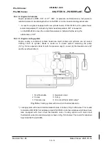
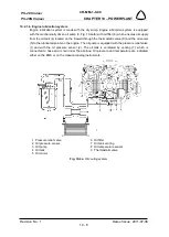
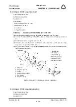
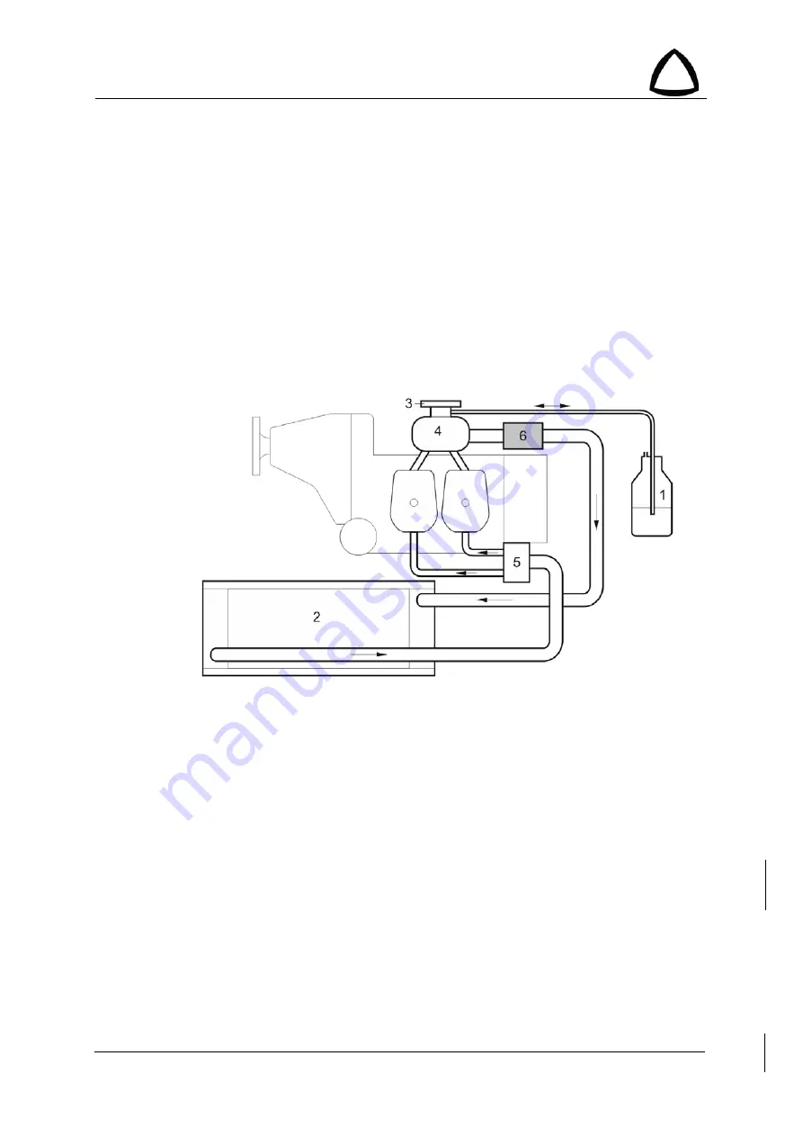
Cooling circuit of cylinder heads is made as a closed system containing the pump
(5, Fig. 10-3a), expansion tank (4) with the pressure cap (3), cooler (2), thermostatic valve (6)*
and the overflow bottle (1).
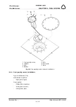
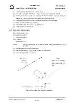
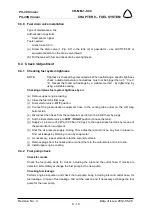
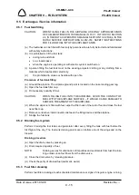
1 Overflow bottle
4 Expansion tank
2 Cooler
5 Pump
3 Pressure cap
6 One circuit thermostatic valve *
Fig. 10-3a
: Cooling system with one-circuit thermostatic valve
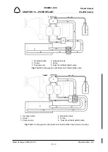
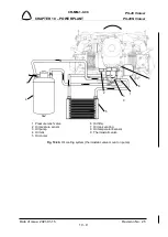
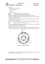
*) cooling system with dual circuit thermostatic valve is shown in Fig.10-3b below. This is valid
for airplane S/N C0547, all airplanes since S/N C0589 or all other airplanes which have been
later equipped with dual circuit thermostatic valve. Cooling system with dual circuit
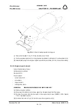
thermostatic valce (mounted on pump) is shown in Fig. 10-3c below. This is valid for airplanes
from S/N C0677 and C0655.

