CR-MM-1-0-00
PS-28 Cruiser
PS-28N Cruiser
CHAPTER 12 – INSTRUMENTS AND AVIONICS
Date of issue: 2021-01-15
Revision No.: 25
12 - 59
(e) Turn on EFIS (external or internal battery power is acceptable). Keep airplane still while
EFIS is powered on. Do not adjust the pitot or static pressures being applied to the EFIS /
ADAHRS while it is powered on.
(f) Verify airspeed and/or altitude reading.
(g) Turn EFIS off (using button 1 is a good option for this operation).
(h) Repeat steps 4-7 for each required pressure point in the test.
12.4.3 Magnetic compass compensation
Rules for doing compensation of the compasses:
(a) Compass compensation must be performed on the approved compass bases, which are
at least 100 m (300 ft) from steel structures, electric leading or other over ground or
underground steel equipment or objects.
(b) If the compass north is westward from magnetic north, the deviation is westward, i.e.
negative. If the compass north is eastward from magnetic north, the deviation is eastward,
i.e. positive.
Compensation procedure:
(a) Turn the airplane to "N" heading; eliminate the deviation by "C" screw.
(b) Turn the airplane to "S" heading; reduce the found out deviation to the half-value by "C"
screw and write down the rest of the deviation.
(c) Turn the airplane to "E" heading; eliminate the deviation by "B" screw.
(d) Turn the airplane to "W" heading; reduce the found out deviation to the half-value by "B"
screw and write down the rest of the deviation.
(e) Turn the airplane by grades indicated in the compensation report (see Tab. 12-3; 12-4)
and write down individual deviations in the table.
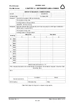
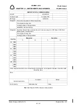
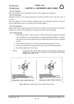
(f) After finishing compensation of the magnetic compass fill out the deviation card (see Fig.
12-45) and position it in the airplane near the magnetic compass.
12.4.4 EFIS compass heading calibration
Procedures are mentioned in EFIS D100 Installation Guide (P/N 100487-000, latest revision).
Procedures are mentioned in SkyView System Installation Guide (P/N 101320-016, latest
edition).
Procedures are mentioned in G5 Installation Manual (P/N 190-01112-10, latest edition).
12.4.5 ADHRS magnetic heading calibration
Procedures are mentioned in SkyView System Installation Guide (P/N 101320-016, latest
edition).
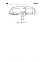
Fig. 12-45
: Example of the deviation card

