


Instructions for Useand
M a i n t e n a n c e
Section
F
15
Stabilising operations
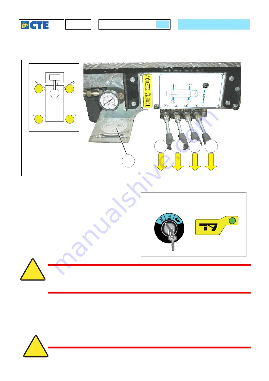
BL
L2
L1
L4
L3
1
2
3
4
SA2
HC3
UM1005
After having assessed the real solidity of the ground
where one must work, it is necessary:
- Turn the selector
SA2
to the left position of
stabilisation selection.
- Bring the four outriggers to the ground lowering
their levers
L1, L2, L3
and
L4
.
- Having reached the desired position, release the
levers which will automatically return to the centre.
ATTENTION
For correct stabilisation, the vehicle wheels must be lifted from the ground, except
for when the manufacturer of the vehicle has prescribed to work with the wheels on
the ground. This information will be inserted in the document attached to the manual
“Work area machine dimensions”.
- Check that the platform is horizontal, as indicated by the bubble level
BL
. If necessary, act on the individual
outriggers to reach horizontal positioning.
- The green light will turn on
HC3
indicating that the boom can be lifted.
ATTENTION
With outriggers and beams out of position, the light H3 in the cabin should be on
Summary of Contents for B-LIFT PRO Series
Page 6: ...Instructions for Use and Maintenance Page left empty on purpose...
Page 14: ...Instructions for Use and Maintenance Section A PAGE LEFT EMPTY ON PURPOSE...
Page 36: ...Instructions for Use and Maintenance Section C 6 PAGE LEFT EMPTY ON PURPOSE...
Page 40: ...Instructions for Use and Maintenance Section C 10 PAGE LEFT EMPTY ON PURPOSE...
Page 100: ...Instructions for Useand M a i n t e n a n c e Section F 28 PAGE LAISSEE VOLONTAIREMENT VIDE...
Page 101: ...Section G Anomalies index Troubleshooting 2...
Page 104: ...Instructions for Useand M a i n t e n a n c e Section G 4 Page left empty on purpose...
Page 126: ...22 Section H PAGE INTENTIONALLY BLANK...
Page 127: ...Section index Demolition 2 Elimination 3 Section H1 Maintenance...
Page 130: ...Use and Maintenance instructions 4 Section H PAGE LEFT EMPTY ON PURPOSE...
Page 148: ...4 Section S Instructions for Use and Maintenance PAGE LEFT EMPTY ON PURPOSE...