9-132
Cisco MGX 8850 Routing Switch Command Reference
Release 2.0, Part Number 78-10467-04 Rev C0, October 2001
Chapter 9
Troubleshooting Commands
dspxbar
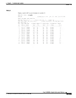
The crossbar configuration consists of four categories of information for each slot:
•
The type of backpressure is always Inband (meaning ingress direction). A crossbar does not have
buffers (as the AXSMs do) and therefore must send backpressure signals to the queuing chips on
each AXSM if congestion begins to occur in the switching plane.
•
The Disable Request field automatically indicates any requests to turn off a source or destination
for the link between the ASIC and the service module. The hardware alone generates the disable
request, so you cannot make a disable request as part of troubleshooting.
•
The Disable Data field indicates whether data transfer has been turned off for source or destination.
In the current product, the field for source and destination always is No.
•
The Redundancy Configuration field shows the mode of redundancy used by the ASIC and whether
redundancy configuration exists for a slot. The redundancy mode is always Remap. Remap means
that the switching fabric automatically maps cell transfers to the correct slot if a switchover occurs
in a redundant pair. Note that, if a switchover occurs, the logical slot number in the endpoint ID
stays the same.
The Slot column for Redundancy Configuration shows whether card redundancy exists, as follows:
if the slot number under Redundancy Configuration differs from the number in the Slot Number
column (far left in the example screen), a card redundancy configuration exists for that slot pair.
Note
From the number of fixed values in the preceding fields, you can see that very little can change in
the crossbar configuration itself.
Cards on Which This Command Runs
PXM45
Syntax
dspxbar [slot] [
plane
]
Syntax Description
Related Commands
dspswalm, dspxbaralm, dspxbarerrthresh, dspxbarerrcnt, clrxbaralm, clrxbarerrcnt
Attributes
slot
(Optional.) The slot number of the XM60. Valid slot numbers are 9, 10, 25, and 26.
Subsequently, specify a switching plane in the range 0 to 3.
plane
(Optional.) The number of the switching plane. If you do not specify a plane, the
system displays information for plane 0 as a default. In an MGX 8850 node, the range
is 0–2.
Log: no log
State: active, standby, init
Privilege: ANYUSER

