5-80
Cisco MGX 8850 Routing Switch Command Reference
Release 2.0, Part Number 78-10467-04 Rev C0, October 2001
Chapter 5
PNNI Commands
dsppnni-node
Example
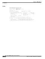
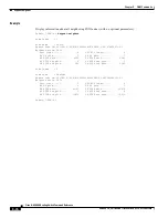
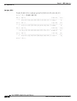
Display details about the current node. This example reflects a node in a single-peer group.
SanJose.7.PXM.a > dsppnni-node 1
node index: 1 node name: SanJose
Level............... 56 Lowest.............. true
Restricted transit.. off Complex node........ off
Branching restricted on
Admin status........ up Operational status.. up
Non-transit for PGL election.. off
Node id...............56:160:47.00918100000000309409f1f1.00309409f1f1.01
ATM address...........47.00918100000000309409f1f1.00309409f1f1.01
Peer group id.........56:47.00.9181.0000.0000.0000.0000.00
SanJose.7.PXM.a >
ATM address
For the constituents of the ATM address, see the description of addpnni-node
or cnfpnni-node. Before you change the ATM address, disable the nod by
executing cnfpnni-node -enable false. See description of cnfpnni-node
Peer group id
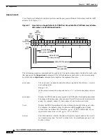
Display the -pgId of length level that is assigned to the PNNI node. The peer
group is the PNNI local group.The peer group consists of all PNNI nodes with
matching pg-id values.
The default value of level is 56 (7 bytes), which specifies the length of -pgId
to 7 bytes. However, the maximum length of -pgId is 14 bytes, so display
commands always display -pgId as 14 bytes with trailing zeros filling the
undefined fields. If you increase the value of level, you change the length, and
therefore the value, of -pgId, but it will always be displayed as 14 bytes.
This is a 14-byte, formatted hexadecimal string. Like all PNNI addresses,
identifiers, and prefixes, this value is portrayed as a string of hexadecimal
“nibbles.” One or several pairs of nibbles entail each parameter field.
(See
Figure 5-7
.)


