5-7
Cisco MGX 8850 Routing Switch Command Reference
Release 2.0, Part Number 78-10467-04 Rev C0, October 2001
Chapter 5
PNNI Commands
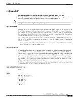
addpnni-node
ATM Address of the Node
A switch-level ATM address consists of:
•
An eight-bit byte that identifies the format of the address. The format is either E.164 or the more
common NSAP.
•
19 8-bit bytes for an ATM address.
•
The last byte of the ATM address is the selector byte.
•
The Selector byte identifies the host application on the switch. Host applications like PNNI single
and multiple peer groups, IP connectivity, and AESA ping have the same ATM address up to the
19 th. byte. The selector byte differentiates between these applications:
–
The selector byte for a single-peer group is 01.
–
The multi-peer group selector bytes are 2–10 and refer to the level of the logical node.
–
AESA ping is 99.
Note
For information on port-level ATM addresses, see the description of addaddr.
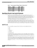
Figure 5-2
Switch-Level ATM Address
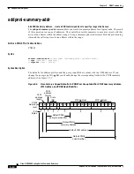
PNNI Logical Node Identifier
A PNNI logical node identifier (node ID) consists of:
•
A number that indicates the level for the logical node within a hierarchy. The current release
supports only one level.
•
The length of the ATM address for the node ID.
•
An ATM address (the same ATM address as the physical switch).
•
In
Figure 5-3
, the level is the default of 56. The length is 160 bits because the ATM address format
is one of the NSAP types—NSAP ICD in this case (as the 47 in the ATM format field shows). For
an E.164 address format, the length of an ATM address is expressed as decimal digits. For the
node-level ATM address, the length is 15. (NSAP address lengths are in bits, whereas E.164 address
lengths are in decimal digits.)
47
1
Number
of Bytes
2
1
1
3
6
6
00 91 81 00 00 00 XX XX XX XX XX XX XX XX XX XX XX XX 00
57114
Cisco
ICD
MAC address
MAC address
Default ATM address

