


5-83
Cisco MGX 8850 Routing Switch Command Reference
Release 2.0, Part Number 78-10467-04 Rev C0, October 2001
Chapter 5
PNNI Commands
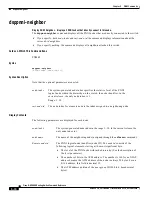
dsppnni-node-list
3.
For levels above the lowest, the node index is appended to the name of the switch. See the node name
column in the display for a multi-peer group in the Example section. For the definition of a node
index, see the description of the dsppnni-node command.
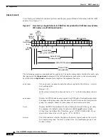
Figure 5-8
Multi-Peer Group
Example of MPG
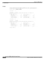
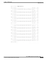
Display all network nodes that are known to the logical nodes on the current switch. This multi-per group
is the basis of
Figure 5-8
. In fact,
Figure 5-8
was constructed from this list. Note that node # 2 has been
either disabled or deleted from the network.
The first graphical representation in this example is
Figure 5-9
. It illustrates where the view of a
particular level begins and ends. As
Figure 5-9
shows, the number of nodes visible at each higher level
decreases. After acquiring a visual grasp of the dsppnni-node-list display, the screen capture that
follows
Figure 5-9
provides a more readable list to examine.
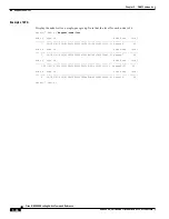
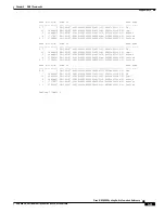
The first series of node numbers is node # 1 through node # 6 and is the list complied by the lowest level
node. As reflected in
Figure 5-8
, mpglax1 is the only node in its peer group, so the first series shows
only one node at level 56. The remainder of the nodes in the first series are the members at the level of
its parent and grandparent, as
Figure 5-8
illustrates. At the levels other than the lowest, the node index
is appended to the switch name.
For the switch named mpglax4, only levels 56 and 40 were configured. Therefore, the display shows the
last node name at level 40 of “mpglax4-02.”
66349
S1-3
Level
40
S4-2
S1-2
S2-2
S1
S2
S4
Level
48
Level
56
Node indexes for switch 1
S1 node index = 1
S1-2 node index = 2
S1-3 node index = 3
Node indexes for switch 2
S2 node index = 1
S2-2 node index = 2
Node indexes for switch 4
S4 node index = 1
S4-2 node index = 2