OPERATION
3-46
Roadie 25K User’s Manual
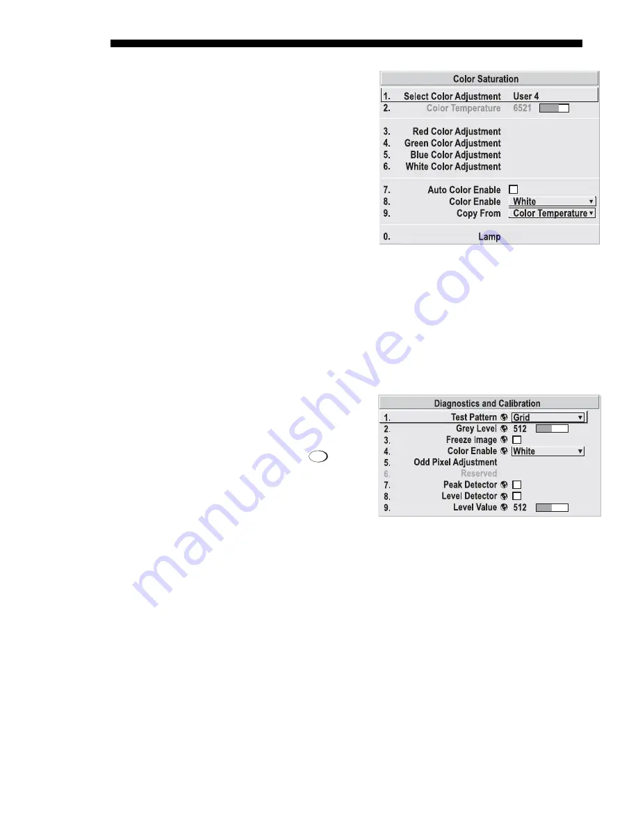
COLOR SATURATION:
Use this
submenu if you do not have
specific color coordinates in mind
and will simply judge color
performance by eye or meter. Like
the Color Adjustment by X,Y
submenu, each color control
actually defines new x/y
coordinates for that color and
changes its hue—it is just a
different interface.
Adjust the hue of each primary
color (red, green, blue, and white)
by using more or less of it in
relation to the other colors. Apply
at any time in the Advanced Image Settings menu.
NOTE: A Color Saturation adjustment defines the corresponding x/y coordinates
shown in the Color Adjustments by X,Y submenu. These x/y coordinates will remain
stable for this “User” gamut until they are changed again via either menu. Values
displayed in the Color Saturation menu, however, will likely fluctuate as you use the
projector, and will be different when you return to this menu at some point in the
future. These floating changes do not affect the x/y coordinates or gamut.
Test Pattern
Choose the desired internal test
pattern to display, or select OFF to
turn off a test pattern.
Alternatively, use the
Test
key for
cycling through test patterns.
Test Pattern Grey Level
Set the desired level of gray for
displaying in the full gray field test
pattern.
Freeze Image
Enter a check mark to freeze (stop) an image at a single frame. This diagnostic tool is
useful if you need to examine in detail a still version of an incoming image that
cannot be “frozen” at the source. For example, in moving images it is sometimes
difficult to observe artifacts such as external deinterlacing/resizing and signal noise.
Remove the checkmark to return back to normal.
Color Enable
Select which color or colors you want to see. This is useful while working with color
temperature, input levels or other special setup parameters. Colors can also be
enabled/disabled by entering the corresponding function code listed on the back of
the standard remote keypad.
Odd Pixel Adjustment
NOTES: 1) Factory-set and rarely required by user. 2) Source must be >90 MHz.
Figure 3.24. Customize Color
System
Configuration
'
DIAGNOSTICS / CALIBRATION
Figure 3.25
Summary of Contents for Roadie 25K
Page 6: ......
Page 56: ......
Page 153: ...SPECIFICATIONS Roadie 25K User s Manual 6 7 ...
Page 164: ......
Page 165: ...Appendix B Remote Keypad Roadie 25K User s Manual B 1 Figure B 1 Standard Remote Keypad ...
Page 166: ......
Page 168: ...SERIAL COMMUNICATION CABLES C 2 Roadie 25K User s Manual ...
Page 169: ...SERIAL COMMUNICATION CABLES Roadie 25K User s Manual C 3 ...
Page 170: ......
Page 186: ......


